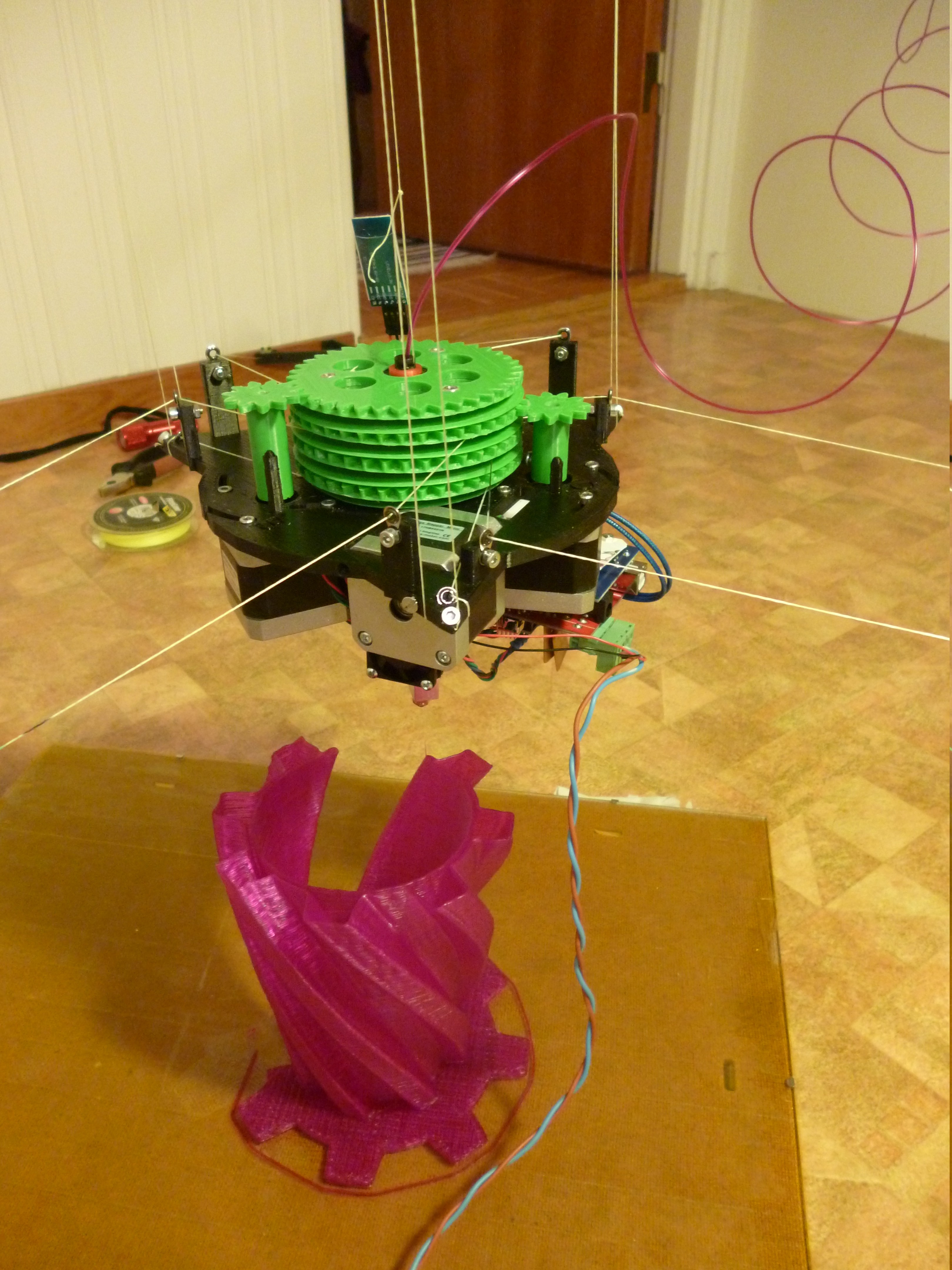
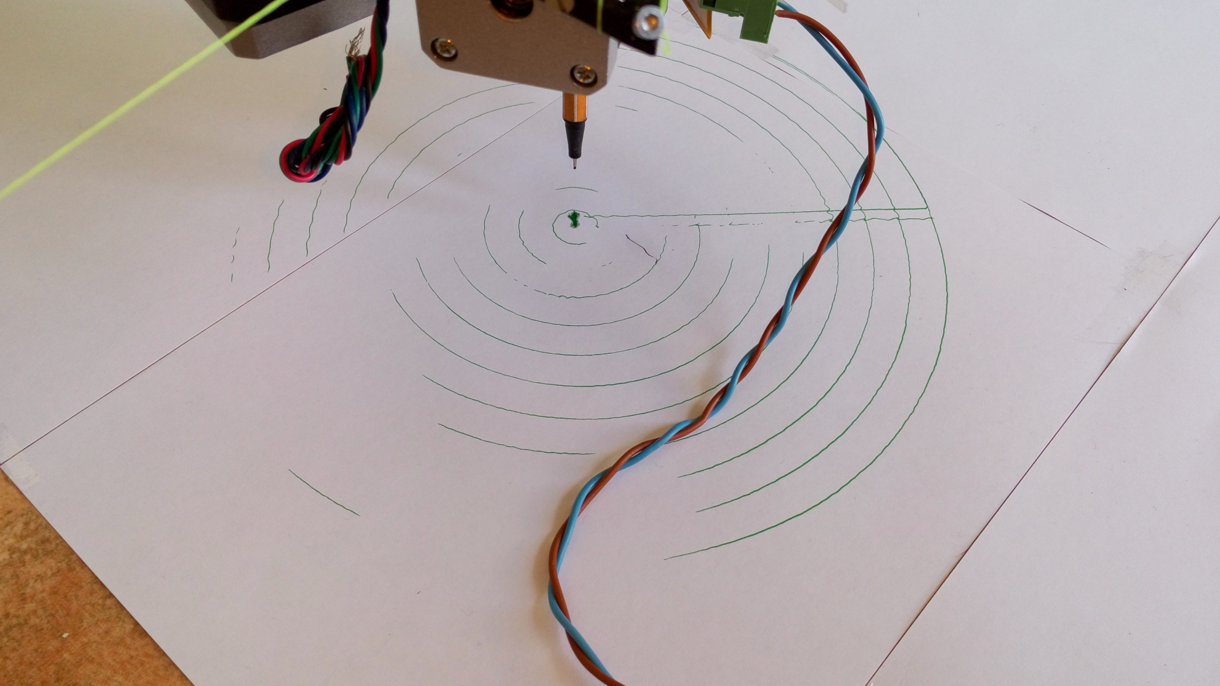
Self replicating responsibly, I promise
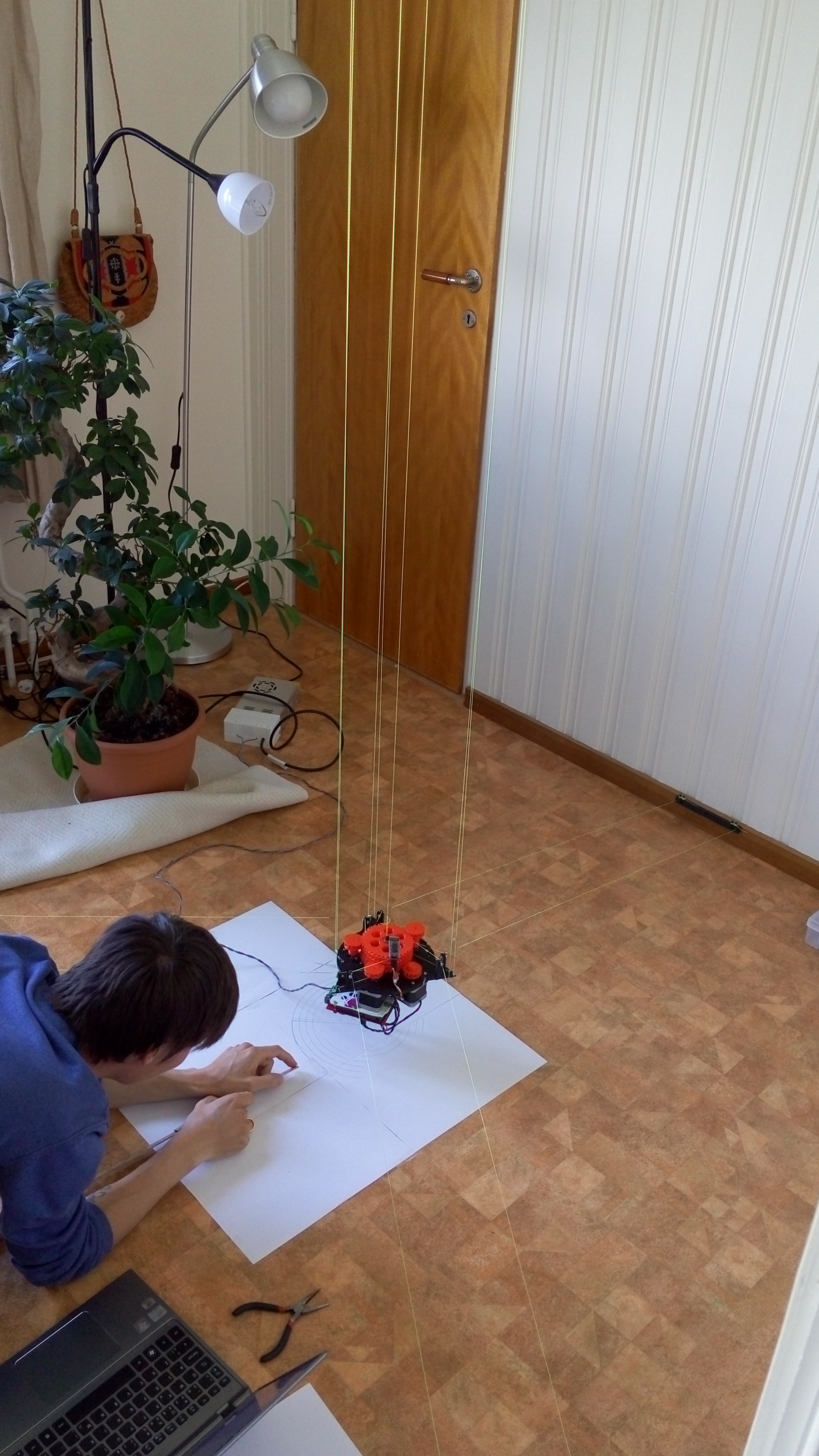
Not only has this thing infested my house, it has convinced me I should help it self replicate on my kitchen floor. How rude! :-O Ok, ok, little on the latest work:
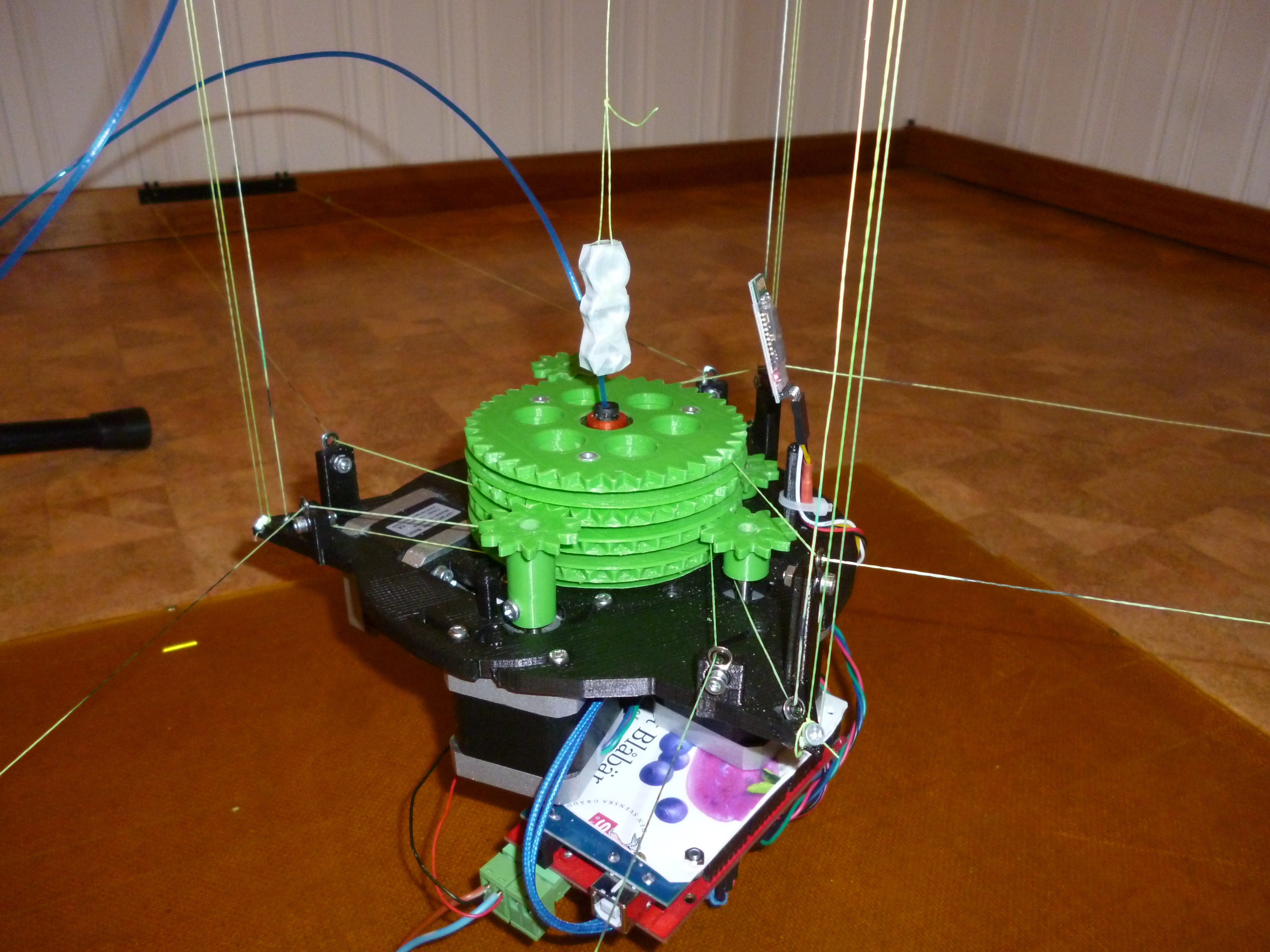
My calibration still isn't top notch, but I'm working on it. To ease calibration I've done three modifications.
- Removed central counter weight and mounted three corner- counter weights. Helps stability, gives less rotation
- Mounted free pendulum (aiming plumb) from the center of the ceiling frame part. Is used when I'm tightening the strings with
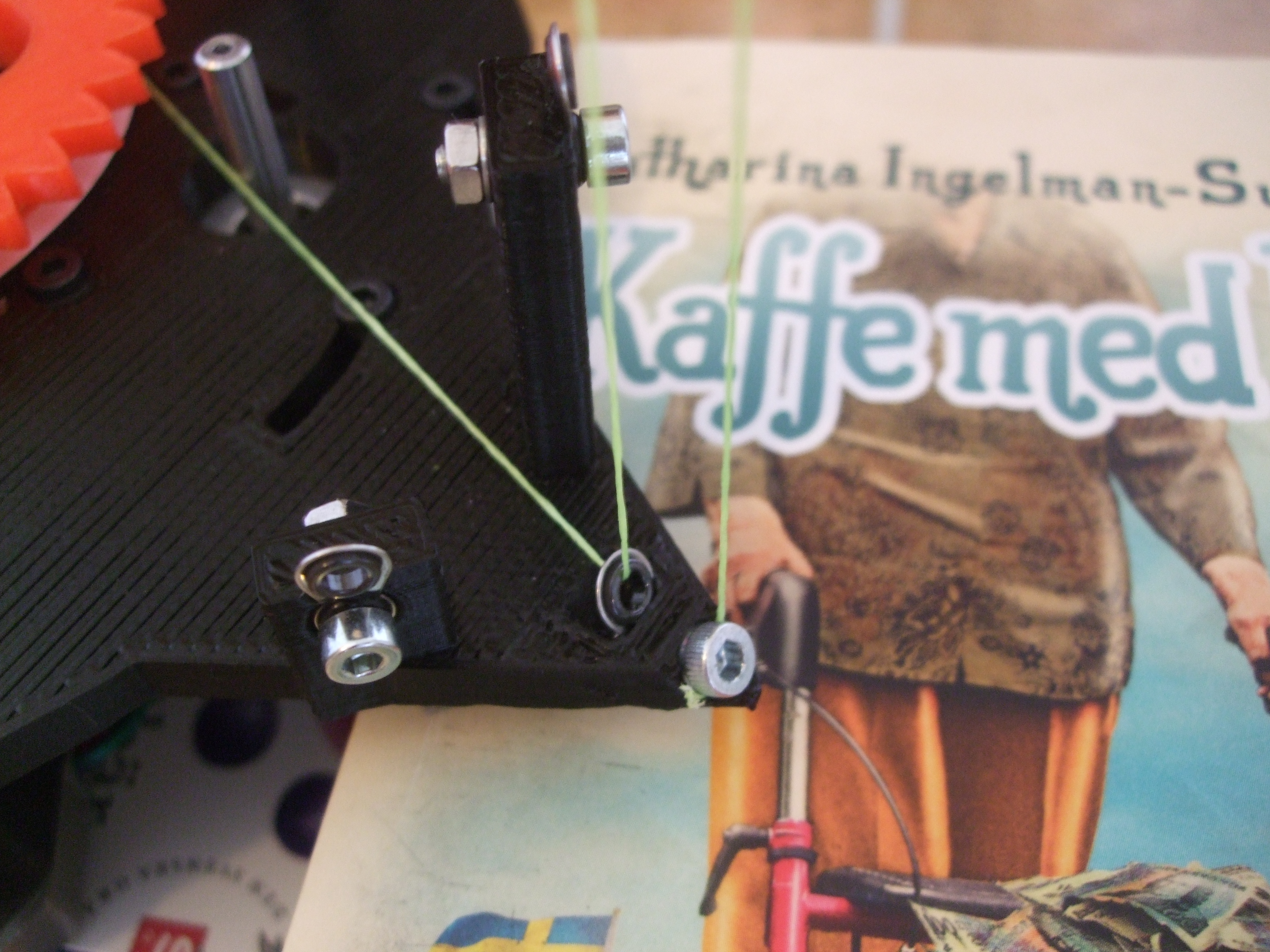
G3 - Gave each parallel string independent adjustment screws
To get some more power, I also geared down the ABC motors by a factor of 2.
As time gets shorter and shorter, as do these posts. So long!
- tobben
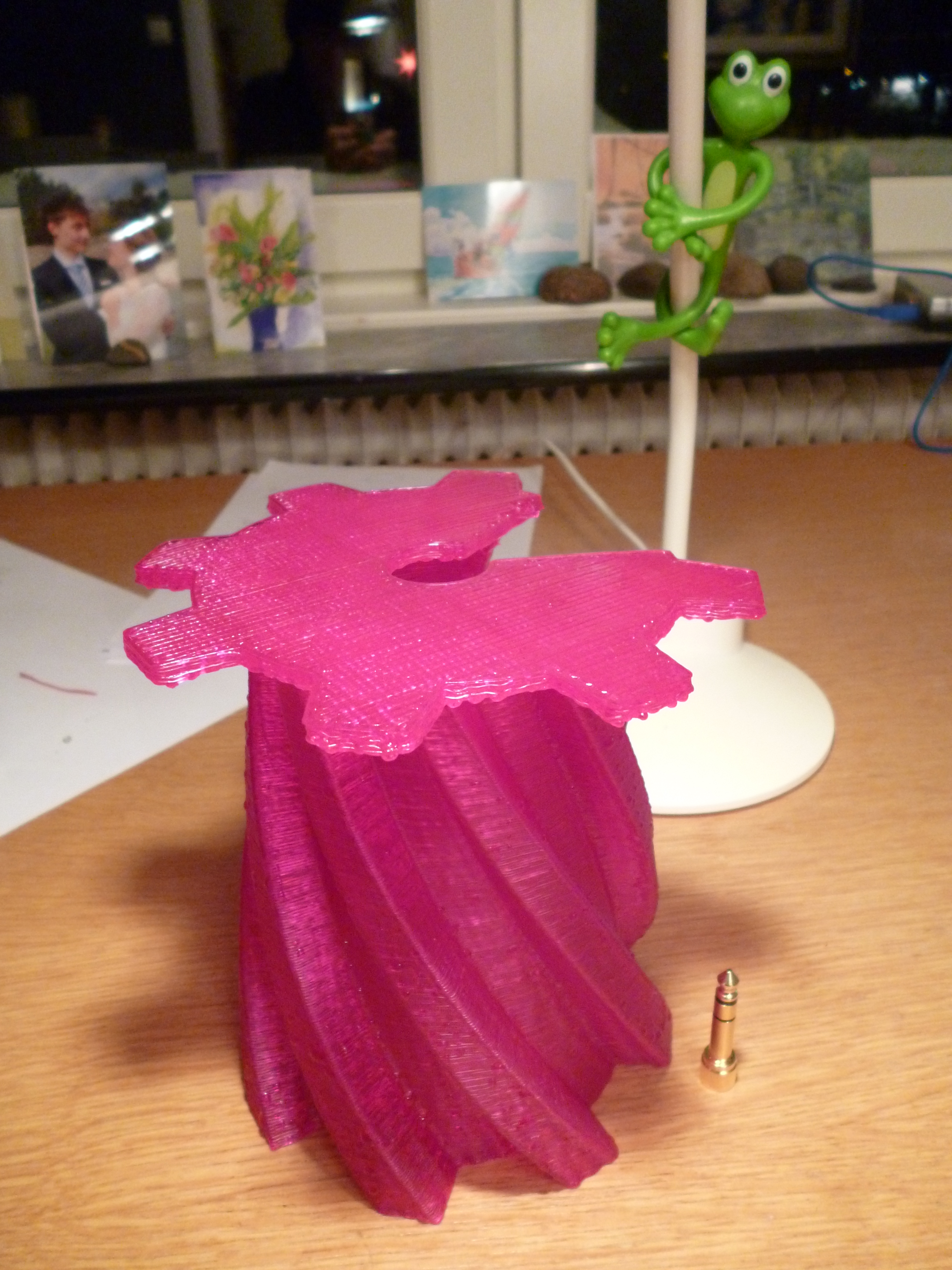
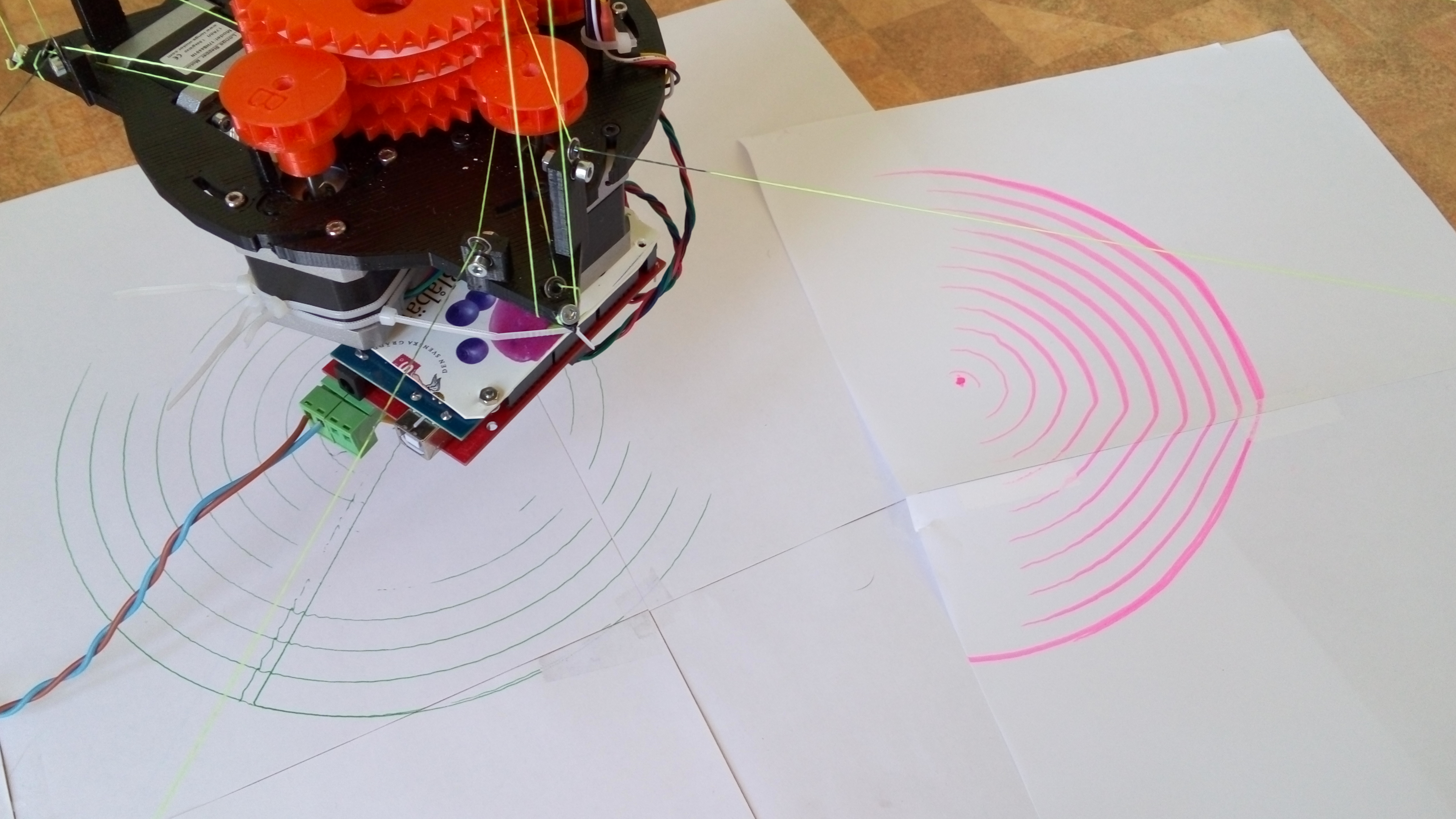
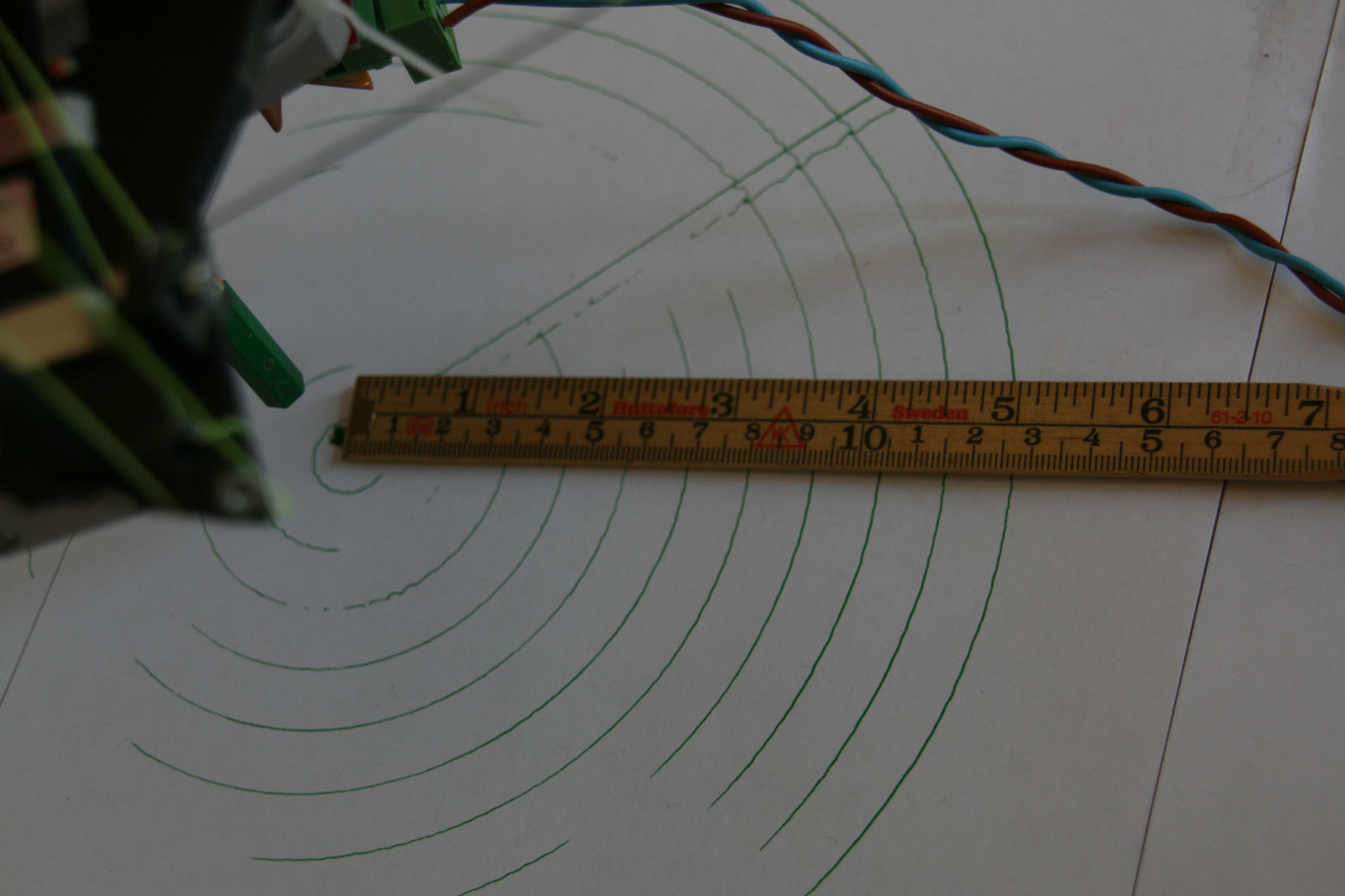
Second finished print
The print was a very exciting one, but I'm very tired so I jump right to...
Lessons learned
- Manual reposition and restart is possible with 10 % print speed and lots of patience. A guiding light strip of light showing the tangent line along which a (possibly paused) Clerck is planning to move next would be very helpful when repositioning half finished prints or confused Hangprinters
- Clerck eats lots of filament. Splicing PLA with candle in the last second is not a recommended approach
- Extruder is not accessible enough
- Coming close to singularities means skipping steps. Plan for this in Slic3r
- The ABC motor closest to its anchor point is always the one (among ABC) with the heaviest load because
- It usually works against pendulum movement
- It has the worst working angle (given that all anchor points are at same z-height)
- When ABC-lines point downwards, more counterweight must be added. D-motor reaches limit when it lifts ca 1.5 kg and has total ca 6 N downwards drag from ABC motors. My D-motor won't do z-lifts (at 40 mm/s) when working against 20 N without skipping steps
- Too few line segments per second make 180 degree-turning ends of rectilinear infill malformed
- Calibration errors' effect grows with distance from origo
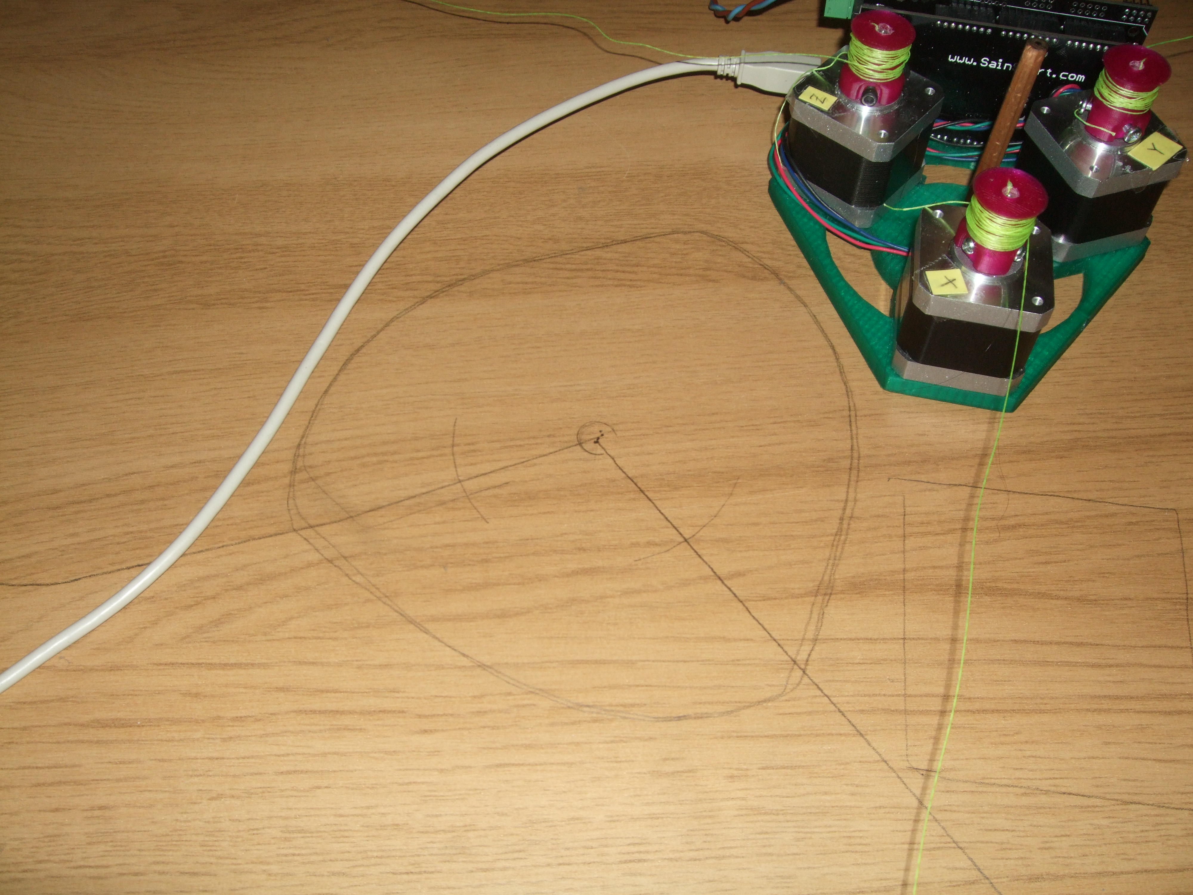
I mentioned after doing the first print that the lines' slack grew with z-height. This was due to calibration errors shown in the figure below
The sketch above shows the angle between ABC-line and XY-plane. Similar sketches apply to angles between ABC-lines and planes in all directions. This explains why the effect of calibration errors grow with distance from origo (point 8 in the list above).
Tightening the strings
When starting the printer, I've noticed that I often want to control the motors individually without affecting
position counters and step counters in the firmware.
I would like the other features of Marlin G1, like jerk look-ahead, acceleration, millimeter units etc.
So I altered the stepping code in stepper.cpp to look like this:
        WRITE(X_STEP_PIN, !INVERT_X_STEP_PIN);
        counter_a -= current_block->step_event_count;
        if(current_block->count_it){
          count_position[A_AXIS]+=count_direction[A_AXIS];
        }
        // wait for drv8825 here...
        WRITE(X_STEP_PIN, INVERT_X_STEP_PIN);
Note that the type block_t got a new count_it member compared to original Marlin.
I then made Marlin accept a G3 command with A, B, C, D and/or E arguments.
When I want to tighten the A and B lines 2 millimeters each, I say G3 A-2 B-2.
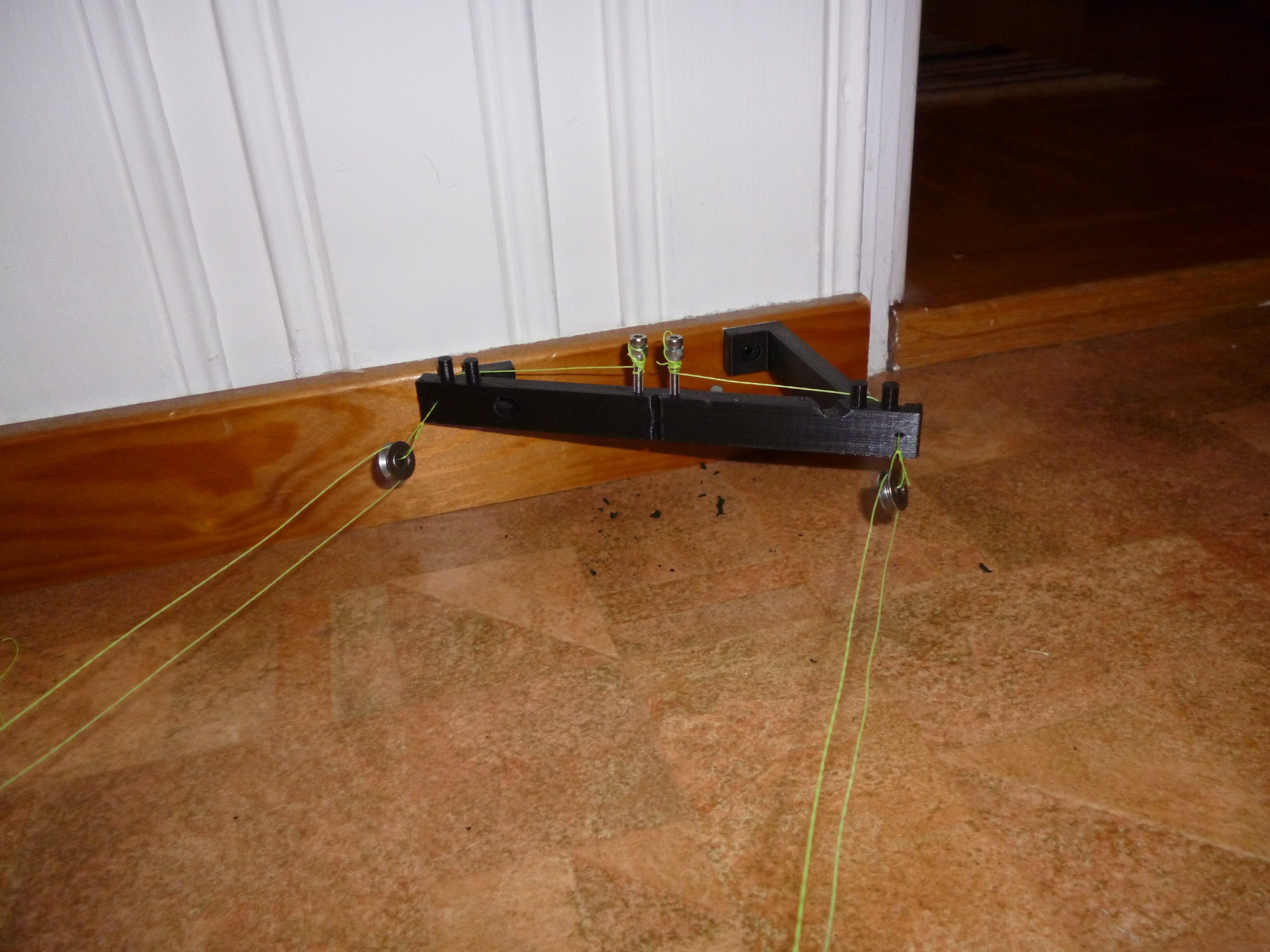
But then there's always the issue with buffering and such during print. A manual way of tightening/loosening comes in handy during long and under-prepared prints like the one in the video above. So I added some length control screws in the ABC frame parts. See figure below.
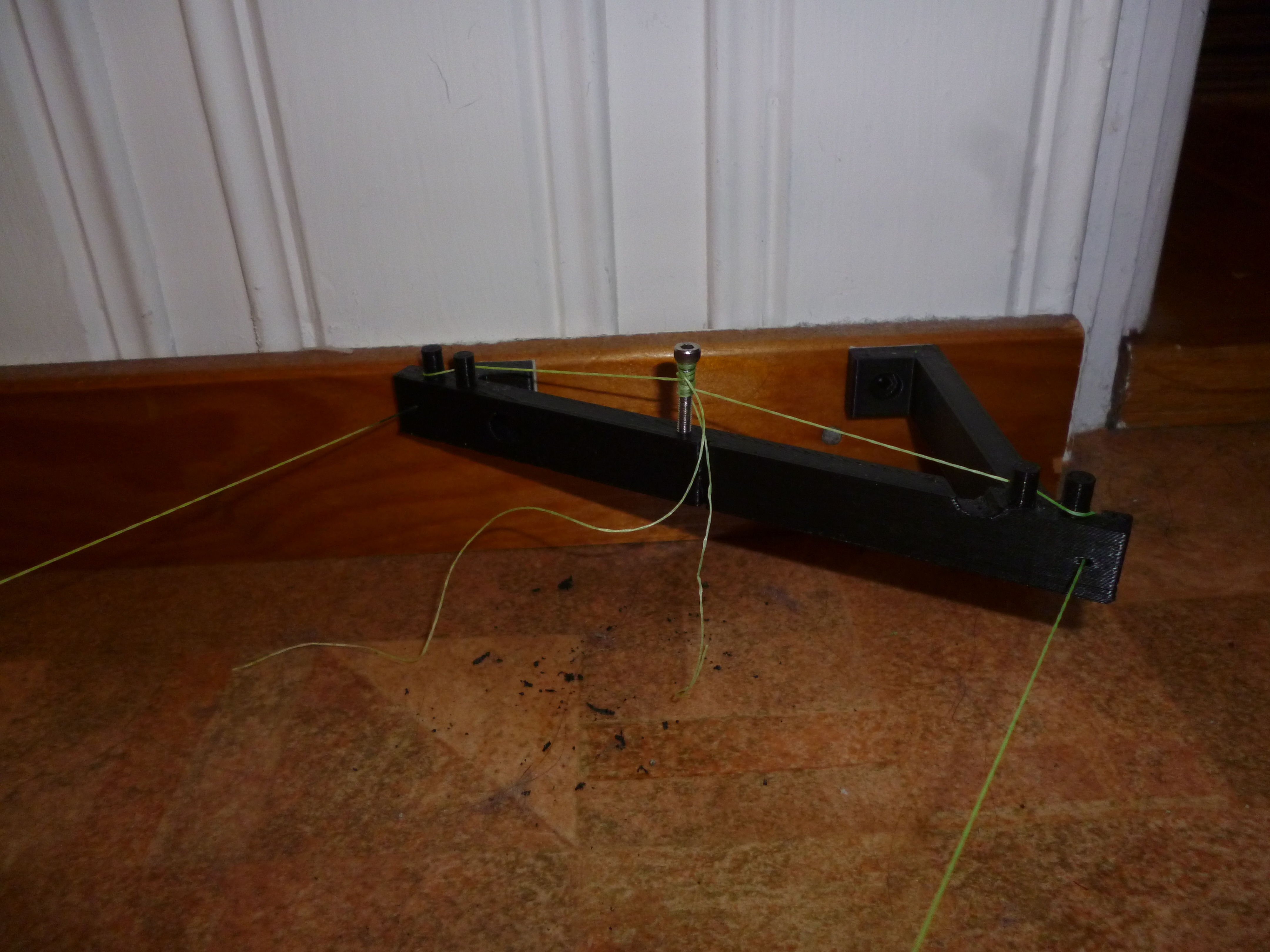
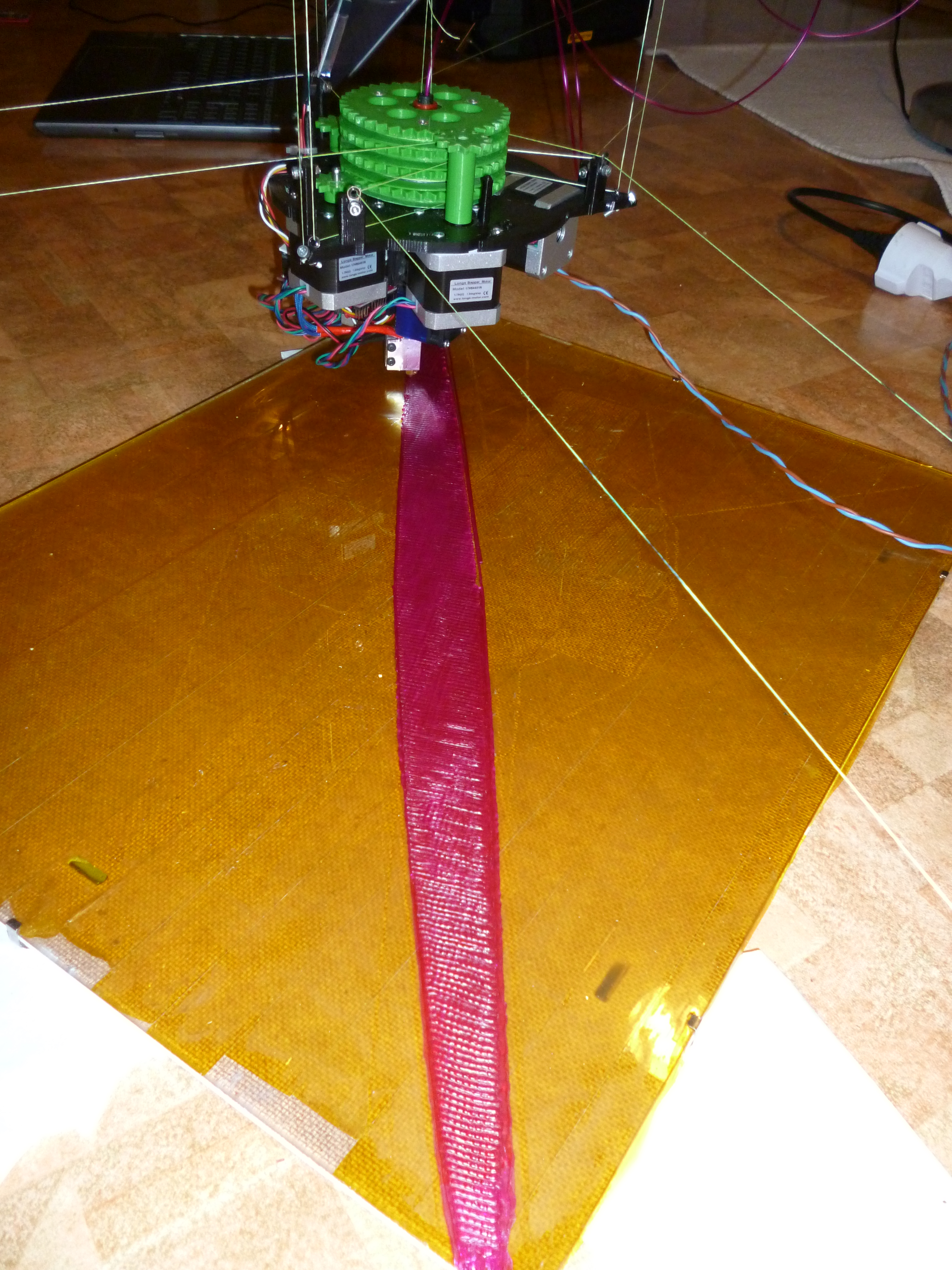
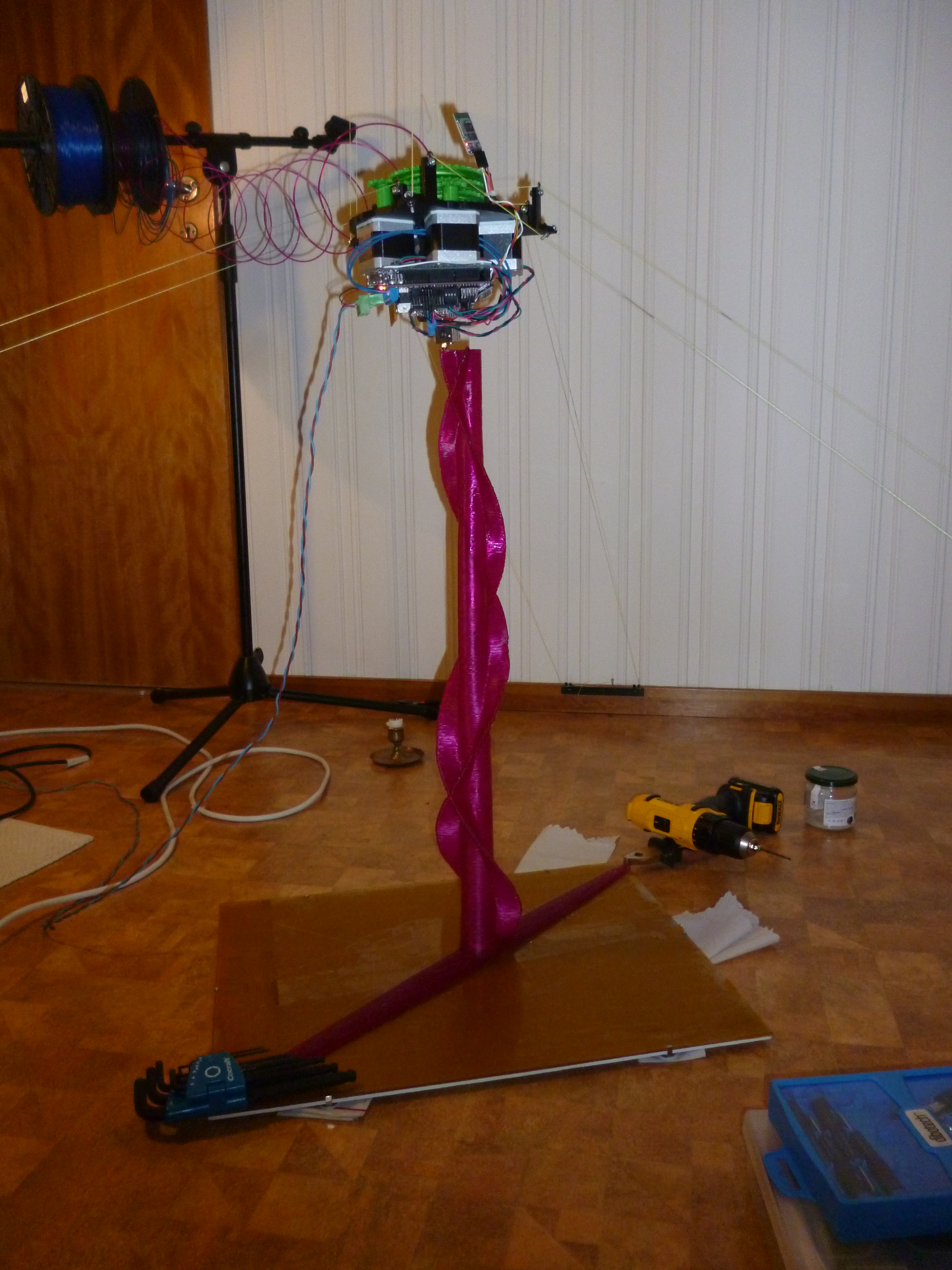
I suspect Clerck's most useful feature is the ability to print long things. Long things get stronger if layers are along the longest direction of the object, so I guess I should be concentrating on first layers. But printing high was a lot of fun.
Plans forward include automatic homeing (see here) and tall, flexible guides to prevent filament and power chords from getting grounded by gears or melted by outside of hot end. Until then, bye bye.
- tobben
CPUs, sqrt and free design hardware
I've been dreaming some more about a full free design, open source hardware tool chain. It might seem like the OSHW movement is a far way from tinkering with free DIY CPUs, but I'm not sure it's actually that far off.
Lack of perceived CPU freedom is partly because of ignorance (well, lack of time), of course. SPARC is open source and that the Intel 4004 schematics are available. However, I don't see many easy-to-build CPUs around.
I'm not a silicon expert, but I suspect that the best place to grow a free CPU project would be within/linked to the excellent AVR and Arduino communities. The first DIY CPU will probably need to resemble currently common (among tinkerers) CPUs, to attract enough contributors. Same logic that made GNU so similar to Unix. Since I hope such an ambitious project will emerge, I'm not a fan of adding complex and expensive 32-bit GHz processors to my RepRap designs.
I know others have good reasons for loving 32-bit.
- Non-Cartesian printers are gaining popularity and speed increases.
- Common firmwares discretizes straight gcode lines tiny line segments.
- These line segments need to be kept very short to avoid visible discretization errors.
I'm no master profiler or optimizer, I'm more a kamikaze-hack-guy, but I thought I'd share a code blob with you.
The rough_sqrt has an error of ca 0.06 mm for an input of 11520000 mm (that is sum of two squared 2400 mm lines).
Error seems to grow like the square root of the input, that is linearly with x and y if used like rough_sqrt(x*x + y*y).
Execution time is somewhere between 80 % and 90 % of the standard (avr-libc) sqrt.
Be warned that it's not well tested, it won't work on NaN, Inf or 0, it will treat negative numbers like positive ones.
float rough_sqrt(float x){
                   /* r21 is iteration exponent
                    * r20.r19.r18 is iteration mantissa
                    * r25 is both input and return exponent
                    * r24.r23.r22 is input and return mantissa
                    * Sorry for not using conventions
                    * r18 = rB0
                    * r19 = rB1
                    * r20 = rB2
                    * r21 = rB3
                    * r22 = rA0
                    * r23 = rA1
                    * r24 = rA2
                    * r25 = rA3
                    * r26 = rBE */
  __asm__ volatile(
"	lsl	r24\n\t"
"	rol	r25\n\t" 		// kick sign bit out
"	cpi	r25, 0xff\n\t"
"	breq	.then\n\t"
"	ror	r24\n\t"
"	rjmp .else\n\t"
"then:\n\t"
"	lsr	r24\n\t"
"else:\n\t" 				// __fp_splitA substitute ends here
"	subi	r25, 127\n\t"
"	clr	r0\n\t"
"	ldi	r26, 0x60\n\t"
"	ldi	r20, 0xa0\n\t"
"	mov	r19, r1\n\t"
"	subi	r24, 0x80\n\t"
"	ror	r25\n\t"
"	brcc	1f\n\t"
"	subi	r24, lo8(-0x40)\n\t"
"Loop:\n\t"
"	lsl	r23\n\t"
"	rol	r24\n\t"
"	brcs	2f\n\t"
"1:	cp	r19, r23\n\t"
"	cpc	r20, r24\n\t"
"	brcc	3f\n\t"
"2:	sub	r23, r19\n\t"
"	sbc	r24, r20\n\t"
"	or	r19, r1\n\t"
"	or	r20, r26\n\t"
"3:	lsr	r26\n\t"
"	ror	r1\n\t"
"	ror	r0\n\t"
"	eor	r19, r1\n\t"
"	eor	r20, r26\n\t"
"	brcc	.Loop\n\t"
"	ldi r22, 170\n\t"
"	mov	r23, r19\n\t"
"	mov	r24, r20\n\t"
"	subi	r25, lo8(-127)\n\t"
"	lsl	r24\n\t"
"	lsr	r25\n\t"
"	ror	r24\n\t"
"	ret\n\t"
                   );
}
I admit I really don't understand everything that's going on in here.
I removed most of my comments because I suspect they contain errors that would confuse a more experienced assembly programmer.
If you want to understand some of it, look for __fp_split3.S and sqrt.S in the avr-libc repo.
This is not a perfect magic solution, its mainly just ignoring bottom byte of mantissa as well as all corner cases.
The approach could be further improved by tailoring a rough_square function with less precision, since the
precision of x*x + y*y is squashed by rough_sqrt anyways.
Is it a drop-in replacement for Marlin's calculate_delta function?
It would be nice if someone more experienced than me would give his/her ten cents, I don't know.
Put it here just to share my thoughts on why someone would put hours into assembly programming pesky 8-bit CPUs.
I should probably approach the Marlin developers with profiling- and code questions.
By the way, I've programmed a bit (maybe 5 - 7 %) on an AVR-simulator. Hope some day we can automate AVR assembly generation (the blob above took hours and hours). An AVR simulator would be one way to work on it. Repo here.
- tobben
Making the Hangprinter project easier to follow
Subscriptions
I've made an RSS feed for this blog. How it looks and how subscriptions work depend on your browser and subscriptions manager. Be warned that this blog is all i one HTML document for now, so loading RSS previews and such will load the complete blog. However, the CSS and markup is so simple that reading the blog within any HTML+CSS rendering program will probably work flawlessly.
It's also possible to follow my Vimeo user.
Table of links
Note that this is a snapshot of links from 27 Nov. 2015. I expect links to start breaking within in a couple of months.
| Source code: | Github repo | [link] quick-link to firmware |
| Licences: | The repo has GPLv2, the blog uses Gnu Free Documentation Licence, the Vimeo videos are CC-BY licenced | Follows FSF's recommendations |
| Blog posts: | [1], [2], [3], [4], [5], [6], [7], [8], [9], [10], [11], [12], [13], [14], [15], [16], [17], [18], [19], [20] | Numbered from oldest ([1]) to most recent ([20]) |
| Development thread: | at forums.reprap.org | Some activity |
| Wiki page appropedia.org: | [link] | Updated |
| Wiki page reprap.org: | [link] | Outdated |
| All videos: | My Vimeo user |
- tobben
First finished print
Hello blog, hello World, hello guys and girls. Did another test print today, and this time it finished.

I will compensate the accumulating slackness of the lines by adding manual tightening screws at each anchor point. In the longer run I will try to get away from 32 bit floats in firmware anyways, since it limits scalability. Having said that, I guess I have to try to implement some kind of custom bignum for 8-bit hangprinter firmwares sometime ;)
- tobben
Meet Clerck, the hanging RepRap
Did the first test print just now:

Even though the driver chip for the C-motor broke after ca 12 minutes of printing, I'm very happy with todays test printing. Broken chips are no surprise since they have taken floor-crashes, very high currents with suboptimal cooling, soldering directly on legs and manual motor turning during this development phase. I'll replace it and print some more tomorrow.
Now that the printer works, it should get a name. Following RepRap tradition, I'm naming it after a biologist: Carl Alexander Clerck, or just Clerck. I chose him because he worked with Swedish spiders a long time ago. The printer moves kind of like a spider with four spinnerets, and I'm Swedish, so it fits. Kind of.
- tobben
Meet the Tble-extruder!
I've called it Tble-extruder here since I think of it as "Terrible extruder" but hope to be able to call it "Table extruder" within a few days. My plan is to print a little table with it when I've got it working.
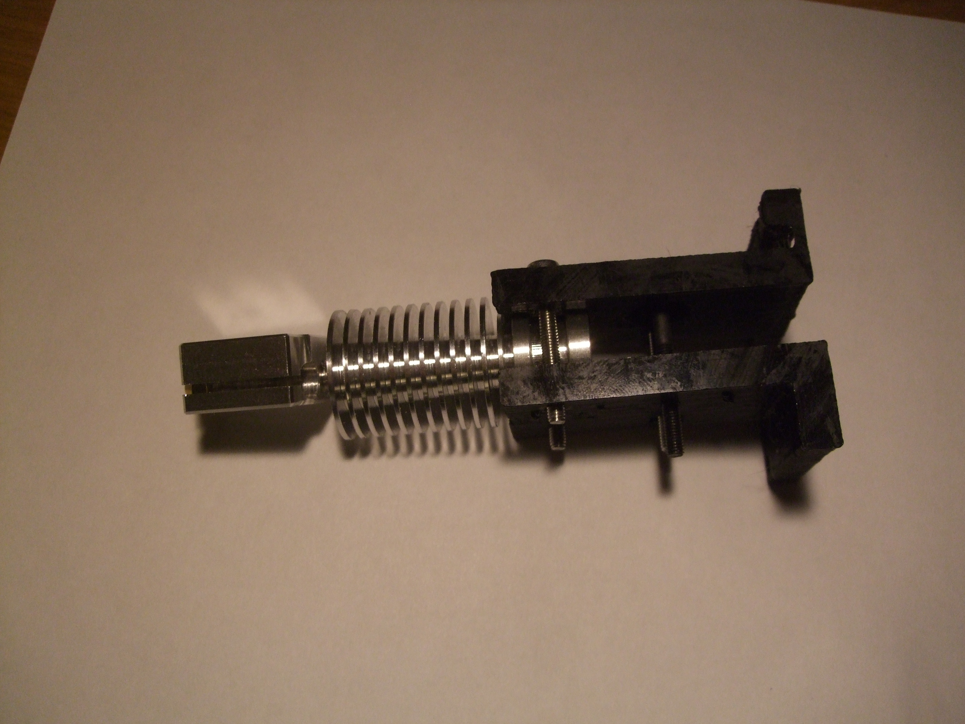
As stated in the previous figure caption, it's been many hours of work so far. The CAD design described in my previous post wasn't really well thought out. Don't follow my footsteps and try to build the extruder described in the previous post. Since it's not very interesting, I've put the list of mistakes in another document (here).
Anyways, putting it together has had its pleasant moments. Pictures of a couple of them below.

- tobben
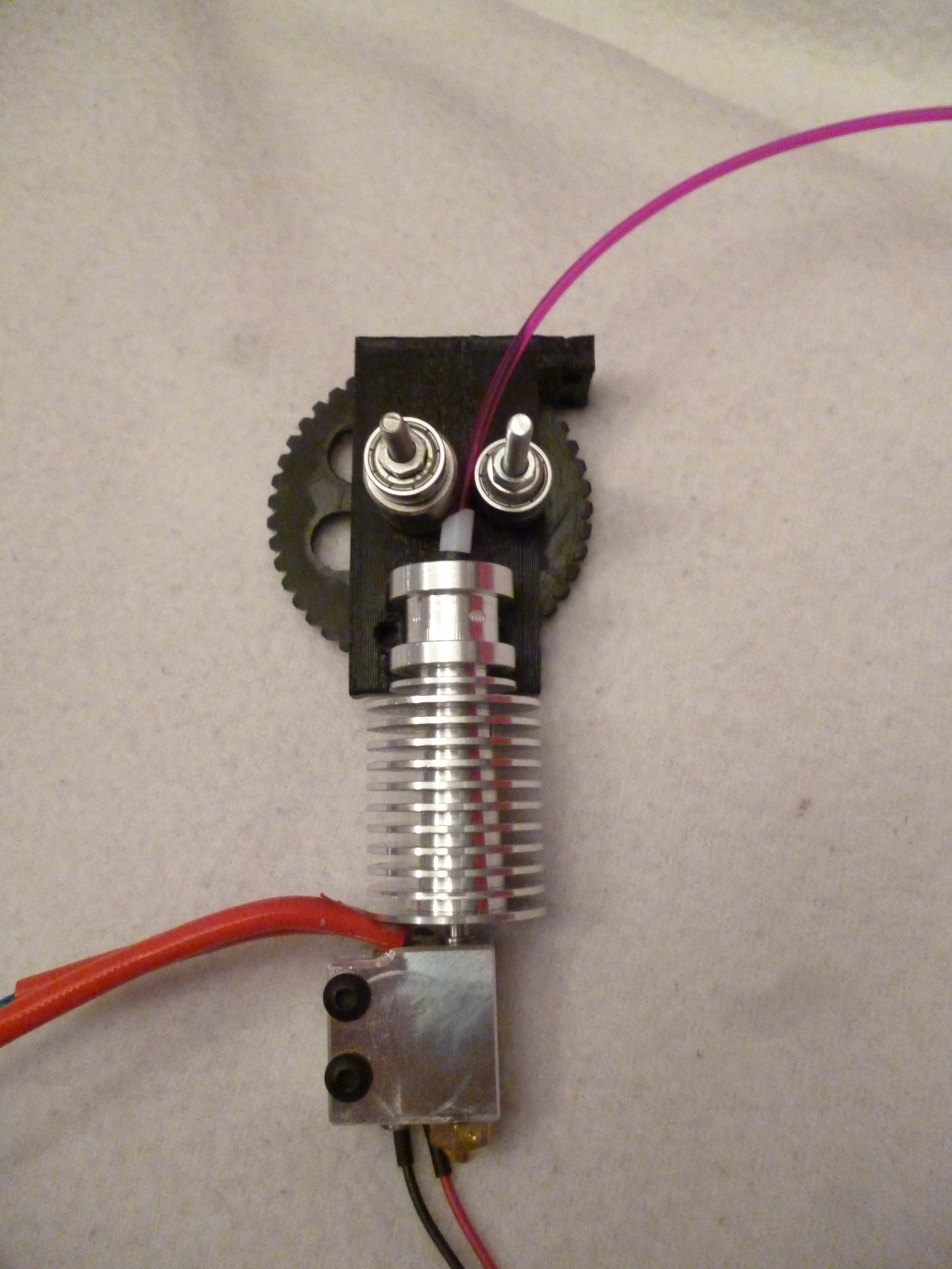
Extruder work
Hi! Just a small update. I've done some design work on the combined extruder and hot end mount.
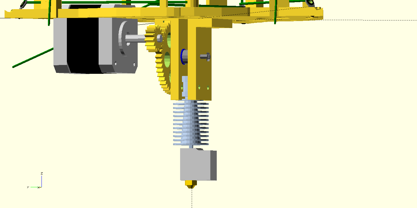
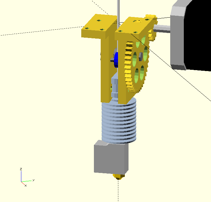
If we're lucky, test printing can start tomorrow =)
- tobben
So what takes me so long?
The last 20 days, I've been writing on this report about the resin 3D-printing market. As a part of solving my bureaucratic problems I needed to complete a 80 hour project aiming to improve the quality of my university programme. I got a request from the head of the programme, and the result is this report.
Be warned that it's probably only interesting for those who read Swedish and hold a fair interest in cheap resin 3D printers...
- tobben
Hardware upgrades and bureaucratic problems
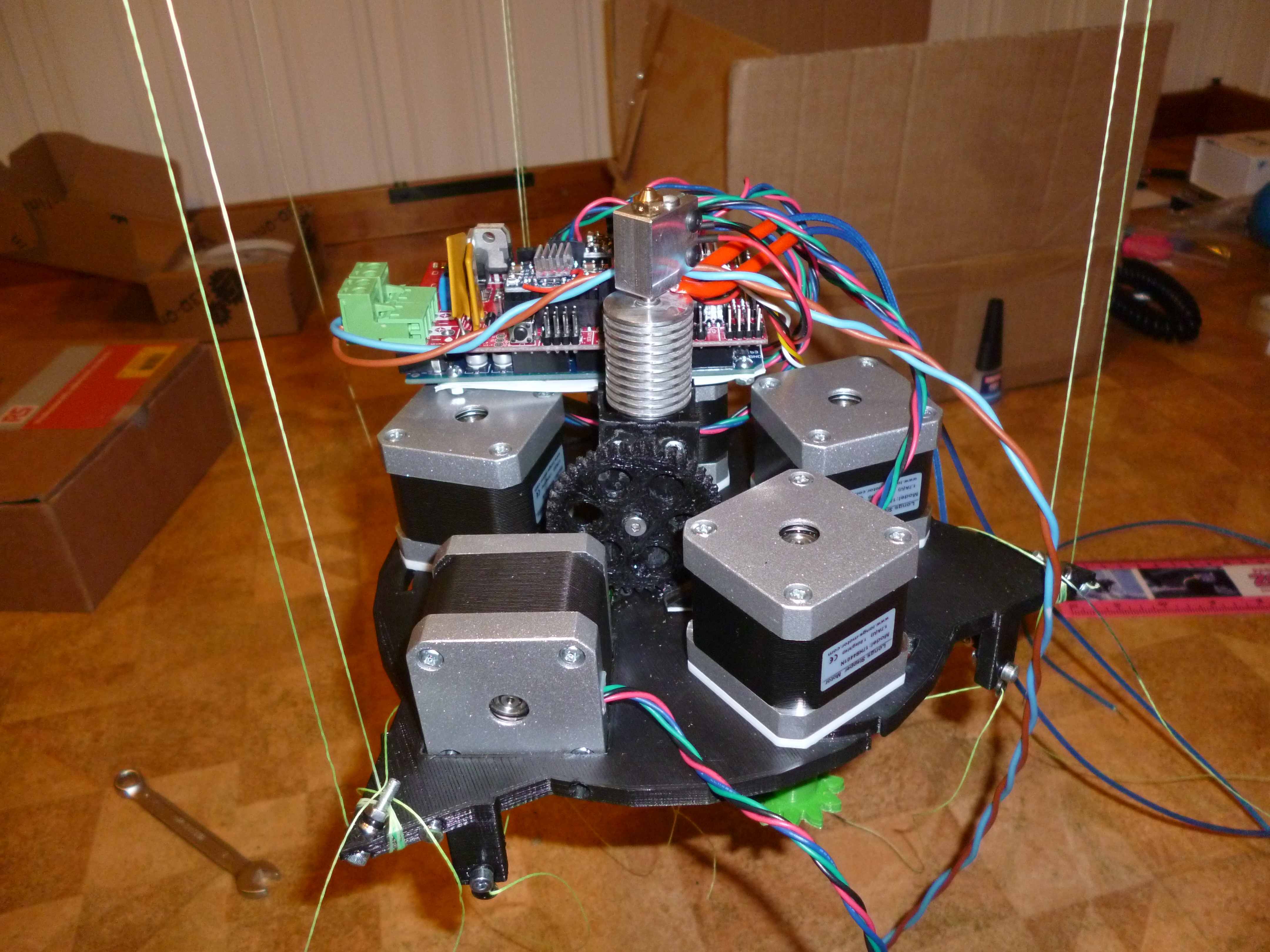
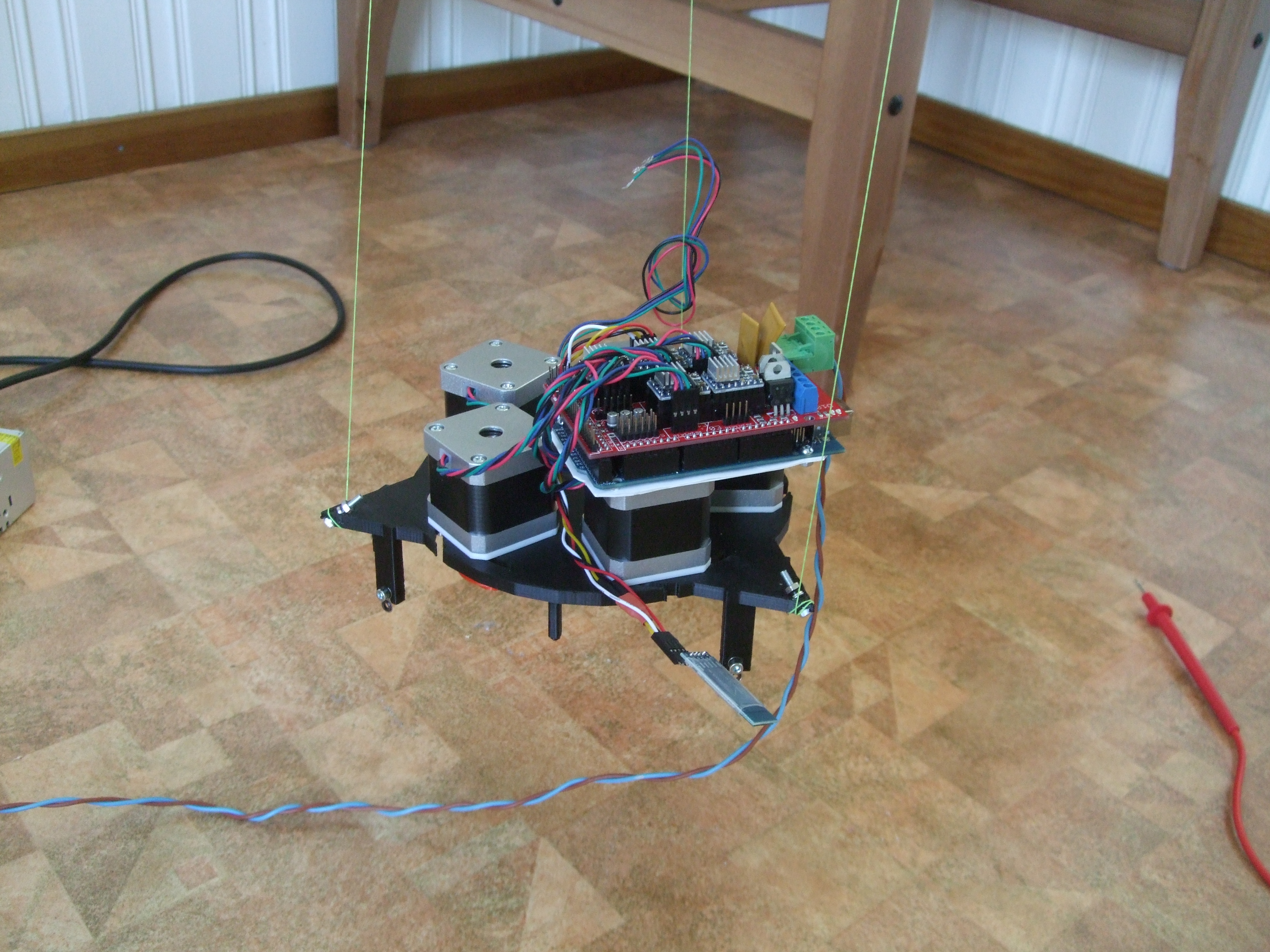
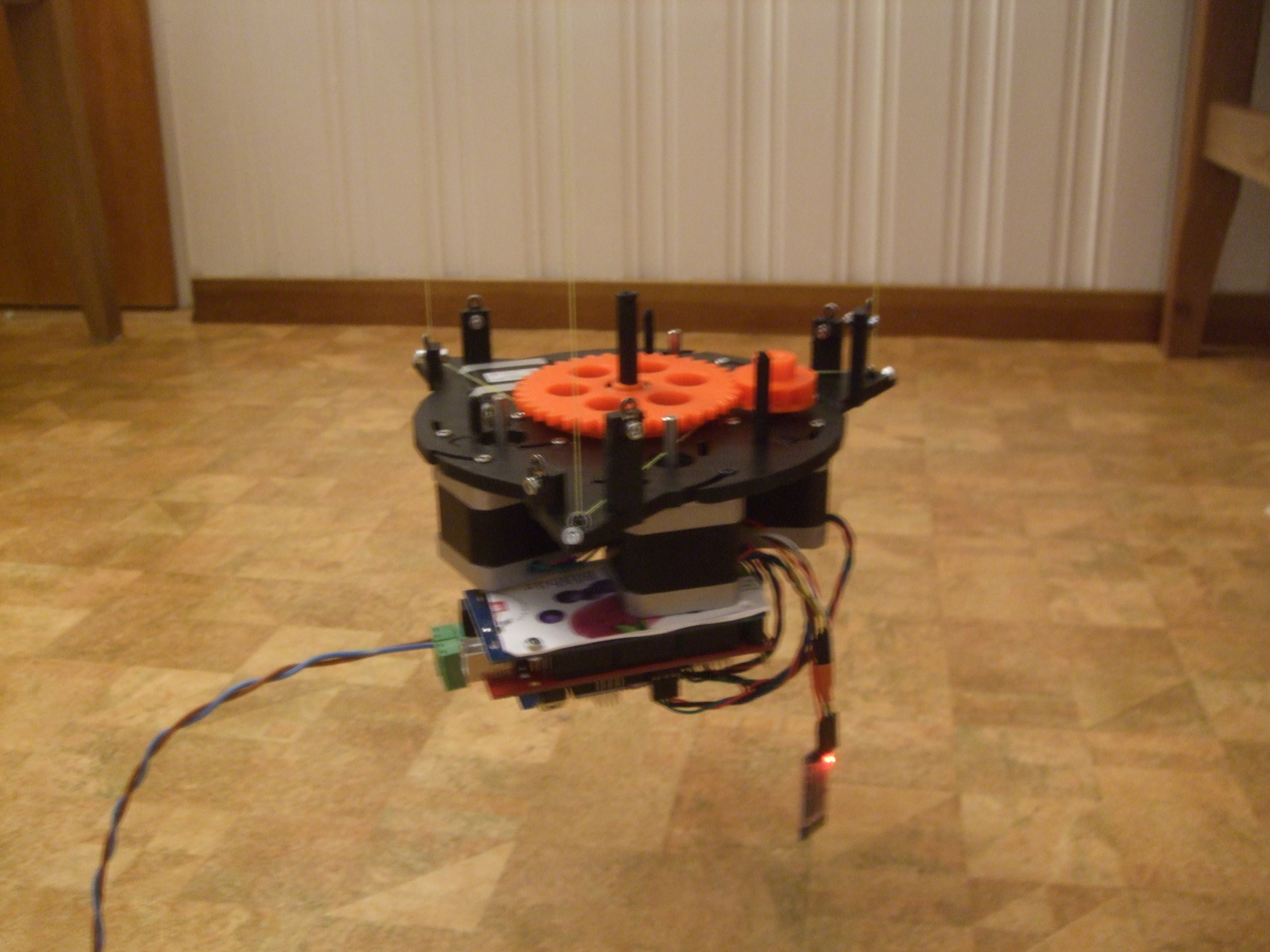
This post has some practical stuff about my master's thesis, but first I want to show you the hardware upgrades in a little video:
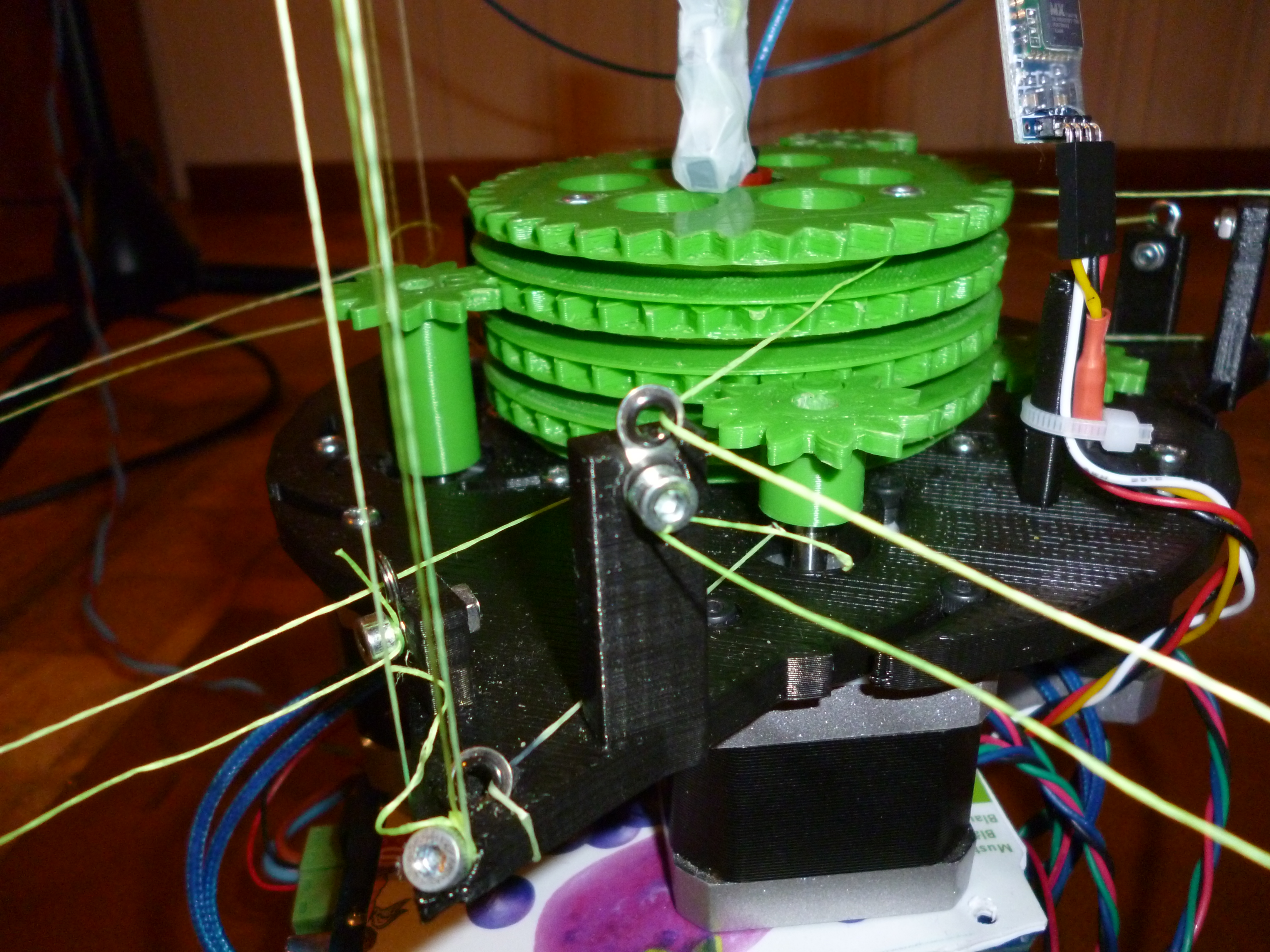
You'll notice that the motor gears and the middle sandwich of spools and gears are changed since the last video. The motor gears now have one tooth less, and the sandwich gears have one tooth more. The spools have also gotten a smaller radius. This have geared the motors down by 14 percent, increasing torque and hence print volume. Since motors spin at only ca 1 revolution per sec (at most when speed is 52.5 mm/s), dynamical torque drops less than 14 percent due to higher speed. That is, gearing down motors gave a net force gain at 52.5 mm/s.
Disks have been added above and below spools to keep the lines in place. Without the disks, I spent more than half my testing time putting lines back in place. With the disks lines have consistently stayed put.
There are still a long wish list of technical improvements, and I expect it to grow.
- A mounted hot end
- An extruder
- Re-mount a modified drv8825 for D-motor (previous one got smashed) and get rid of counter weights.
- Feeding the stepper drivers a higher voltage than 12 V would give stepper motors more torque. Higher voltage will give the stepper driver the possibility of increasing motor current faster. Experience shows that the drv8825 is able to take advantage of this, resulting in more motor torque.
- Faster code for computing
sqrt((x-x0)^2 + (y-y0)^2 + (z-z0)^2)would allow more segments per second/a smaller processor/more closed loop processing. - A cheap accelerometer and gyroscope (like the MPU-6050 datasheet) would enable both automatic homing (think crashing hot end into build plate style) and some other closed loop feedback. Excellent free code to build upon is found in the FreeIMU project. Since print times will be long, closed loop feedback is highly desirable.
- Using
nopfor timing the drv8825s wastes up to ca 4000 processor cycles per second (52.5 mm/s ref speed, 1/8 stepping). This is only 0.025 percent of 16 MHz, but a pure waste. Doubling speed and quadrupling microstepping would give 2 percent waste. Notice that this waste can not be reduced by increasing processor frequency.
However useful the improvements above, they probably won't be deployed soon. I'll explain why in the second part of this post.
The second part of this post
My engineering studies contain university courses from two different Swedish universities. Accreditation complications has forced me to move back across the country and study undergraduate math again for six months. Because of this and my former supervisor's schedule, I'm now searching for new external supervisor for my half-finished master's. We have two supervisors involved in a Swedish engineering masters: one from within the university and one from a company or another university (the external one). I'm searching for a new external supervisor for this project. My new external supervisor will get paid for the full master's. Any suggestions regarding master's supervision? Please email me at tobben(AT)fastmail(DOT)fm or post to the forum.
- tobben
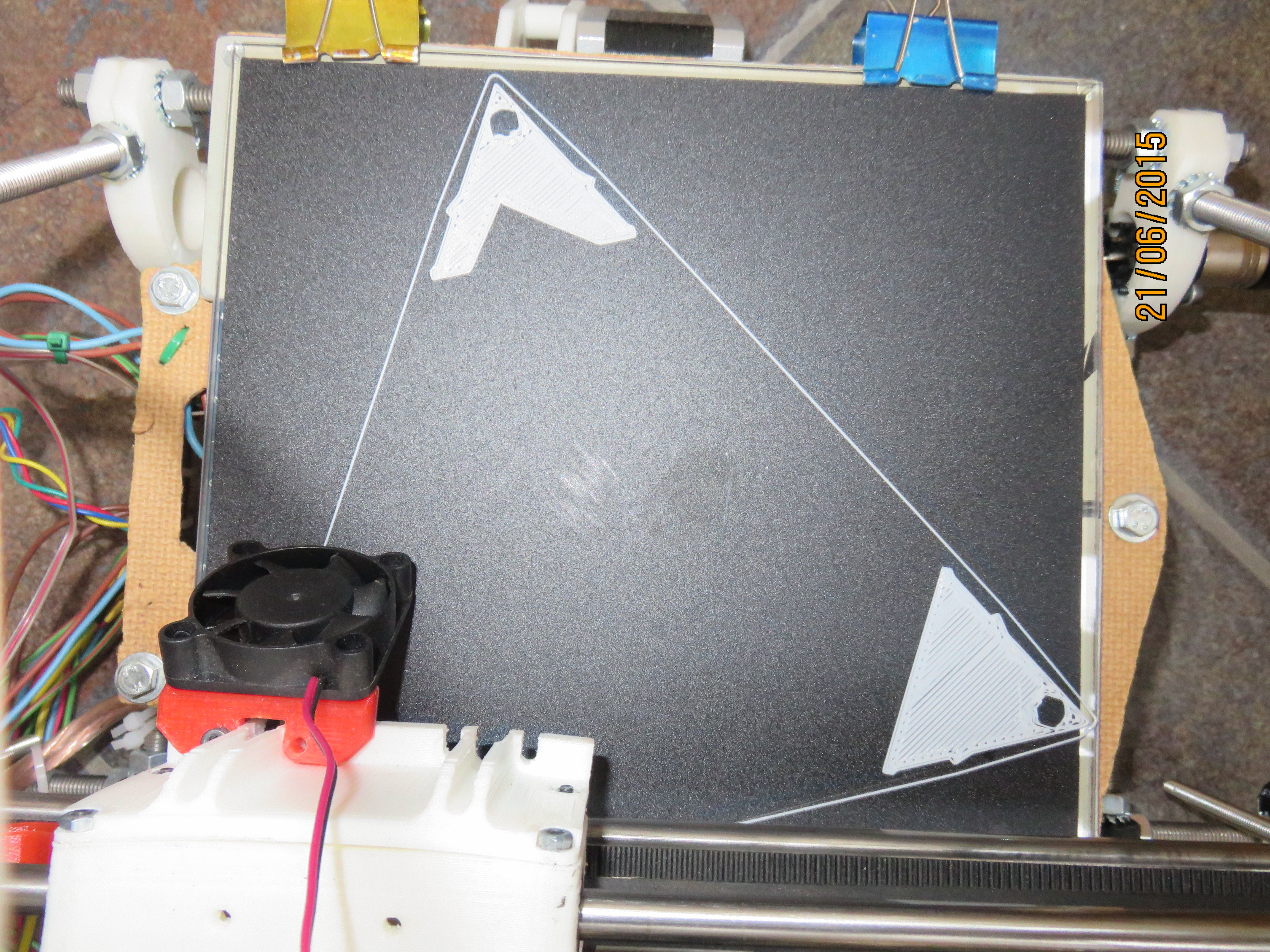
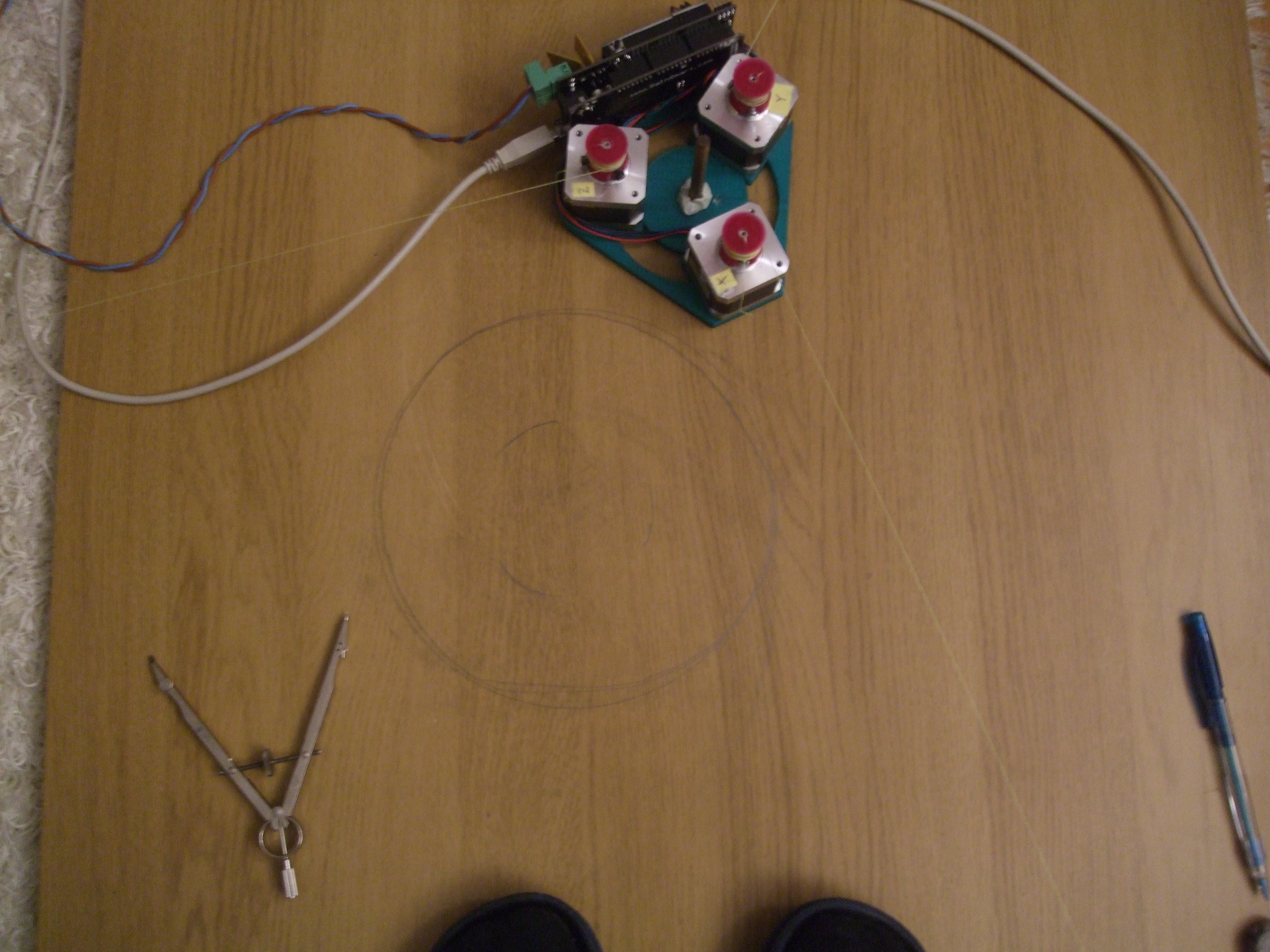
Pics from calibration
Thought I'd just post some pictures from the calibration run yesterday.
I'm going into hardware upgrades for some days now, so update frequency may slow down.
- tobben
More progress
As it turned out, I had made a 5 cm mistake when measuring positions of anchor points. Did one print today with much better precision:
- tobben
Some progress..
Today I'm kind of split in two. One part of me is very satisfied with having a moving robot, even though precision is ~ 1cm. I want to play around with it, make it go high, low, fast and slow.

I'm also happy because as a first prototype, Hangprinter has shown to be a rigid enough construction for things like 3d-printing, when calibrated such that 4 or more abc-lines stay tight, as this video shows:
On the other hand, some large improvements need to me made before further testing can get up to speed. Here's a little priority list for myself:
- Spools need to keep lines in place.
- The power supply should be at a higher voltage.
- Eyelets are too large.
- The extruder motor should be mounted so that direct feed is possible
- The printer is too heavy.
Point 1 is the most important one, since stray lines makes testing really slow.
Points 2-4 are not super important, but they add upp. A higher voltage power supply would give motors a higher torque, and maybe cure my DRV8825 drivers from the high pitch noises they make in my motors. A higher voltage would also allow us to use thinner power supply cables, which is good. I have ordered four NEMA14 motors. This saves us 360 g and some space, so we can make the printer smaller.
I have thought a lot about using suspended weigths instead of the d-motor. The problem with that is holding it down. With anchor points 1 - 2 m away, and only 5 - 15 cm difference between anchor point and action point, the tension in the abc-lines (together) need to be 10 - 20 times the tension in the d-lines (together). We could fine tune the weigths so that we only have 1 N pulling upwards. According to my rough estimations, we would still lose 3 - 6 N cm of dynamic torque.
The gears on Hangprinter has an effective radius very close to 1 cm, so we use N and N cm without converting factor. My testing shows we have only 18 N cm dynamic torque in our Nema 17s (I expect the ordered Nema 14s to have only half of that). With an expected mass of ca 2 kg, the Hangprinter will need a force of 18 N to reach an acceleration of 9000 mm/s^2 (default max acceleration in Marlin). Even if we lower our expectations drastically from 9000 mm/s^2 down to 2000 mm/s^2, the most difficult working angles will steal enough force that we don't have 3 - 6 N cm to spare on each motor.
It seems like 3 beefy abc-steppers working at difficult angles and 4 smaller steppers working at ok angles will give similar results. It would be very interesting to build both, compare them and feel the difference...
- tobben
Hangprinter has climbed its first climb
Just now, the Hangprinter was able to climb upwards for the first time. To make it a bit easier, I halved the needed force by using small v-groove bearings as pulleys in the ceiling frame part.
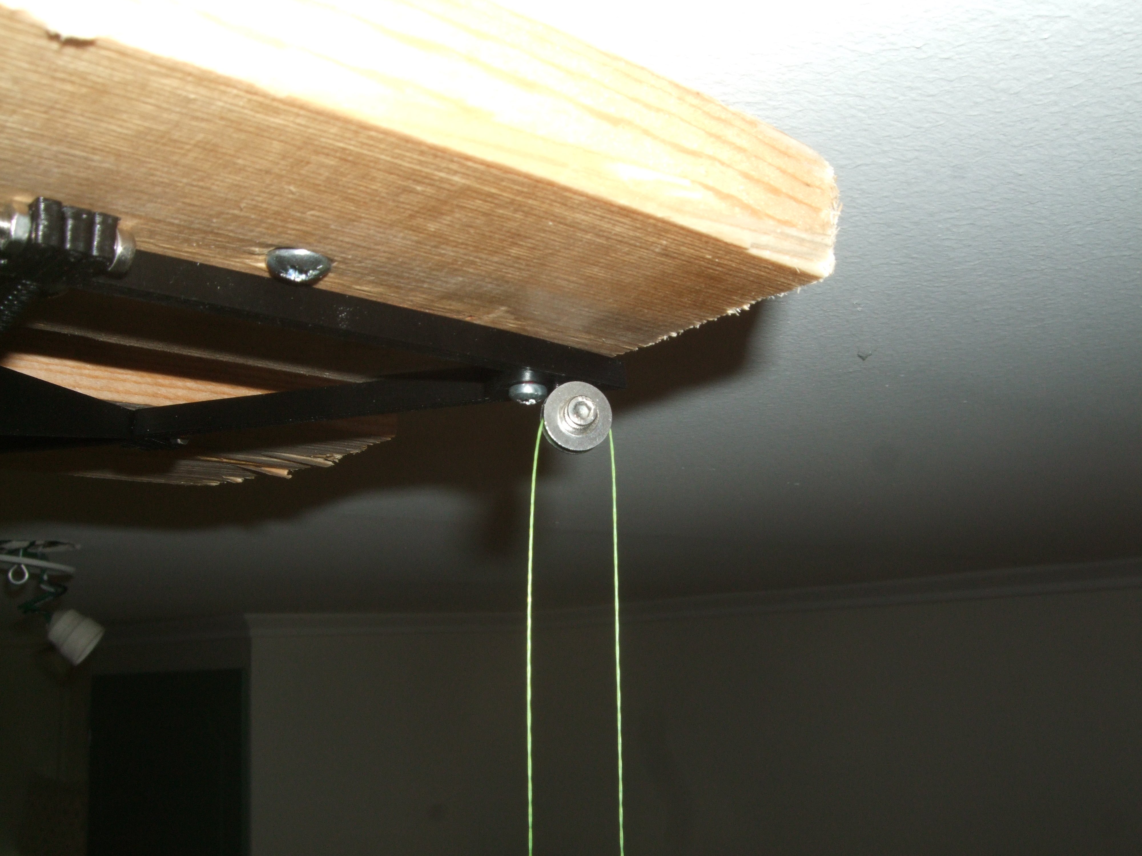
Although I wrote in my last post that I would try to use full step mode, I realized that millimeter precision on the D-axis (towards ceiling frame part) is not really what I want. Layer heights are usually expressed in micrometers, so I decided to go for 16 microstep mode. Together with the pulley-arrangement, this gives Hangprinter ca 90 microsteps per mm, or ca 11 micrometer per microstep.
Since microstepping reduces the holding torque of the stepper motors drastically (with 16 microsteps/step, you only have ca 10 % holding torque left), Hangprinter definitely needed some extra power. I mounted a DRV8825 breakout board and ramped up the current to 1.4 A. Both the motors and the driver are rated for higher currents, but I'm kind of nervous about getting a short thermal shutdown of the DRV8825, as it would crush the printer to the floor. Avoiding such a crash is the sole reason why I go for DRV8825 instead of the quieter and more easily handled a4988. Changing the stepper driver did introduce some extra work, though.
DRV8825 needs longer pulse width than Marlin is used to sending
For solving this, I used five "nop" assembly operations. In stepper.cpp
if (counter_d > 0) {
  WRITE(E1_STEP_PIN, !INVERT_E1_STEP_PIN);
  counter_d -= current_block->step_event_count;
  count_position[D_AXIS]+=count_direction[D_AXIS];
  WRITE(E1_STEP_PIN, INVERT_E1_STEP_PIN);
}
if (counter_d > 0) {
  WRITE(E1_STEP_PIN, !INVERT_E1_STEP_PIN);
  counter_d -= current_block->step_event_count;
  count_position[D_AXIS]+=count_direction[D_AXIS];
  __asm__ volatile(
    "nop\n\t"
    "nop\n\t"
    "nop\n\t"
    "nop\n\t"
    "nop\n\t");
  WRITE(E1_STEP_PIN, INVERT_E1_STEP_PIN);
}
Each nop instruction takes one processor cycle, so five nops gives a 5/16k = 312.5 ns longer pulse width. This gave the shortest working pulse width I found.
Stepper motor stutter, uneven microsteps
When running the stepper slowly, I noticed the exact same stutter problem that is shown here (Youtube-link). The problem is that the mixed decay mode of the DRV8825 doesn't work properly with my motors, so setting it to fast decay mode was necessary. It was Quentin Harley that put me on the right track with this post.

Hangprinter is flippable
Finally, here is a video of the Hangprinter climbing its first climb.
- tobben
Hangprinter has hung its first hang
Mounted Hangprinter frame in the ceiling today. The poor little Nema17 was too weak to climb upwards without some help. Will put it in full step mode and give it some more current tomorrow. If that still isn't enough, I will print new gears (gear it down). Having pulleys in the top frame part, effectively gearing down almost half the force needed, is the next option I'll try. Using rolling fairleads on the Hangprinter itself might just be worth it after all.
Both gearing down and adding bearings introduces risks of greater errors. I save the complicated analysis of them for another day...

- tobben
Hangprinter had its first dry run
Hello again! Just thought I'd share progress again. The Hangprinter has gotten its firmware and bluetooth module working =) Video:
- tobben
Summer update on the Hangprinter
Hello folks! Just wanted to share some progress.
OpenSCAD Work
The scad-files have gone through a big reorganization and refinement. I had the insight while hacking on the firmware that a lot of constants will be shared between the firmware and the scad-files. Therefore, I tried to parametrize the CAD-files with as straightforward parameters I could come up with and put all the parameters in a file called design_numbers.scad. When the time comes to compile and upload the firmware, one may (should) make a little script that parses design_numbers.scad into design_numbers.h, compiles Marlin and removes design_numbers.h immediately afterwards.
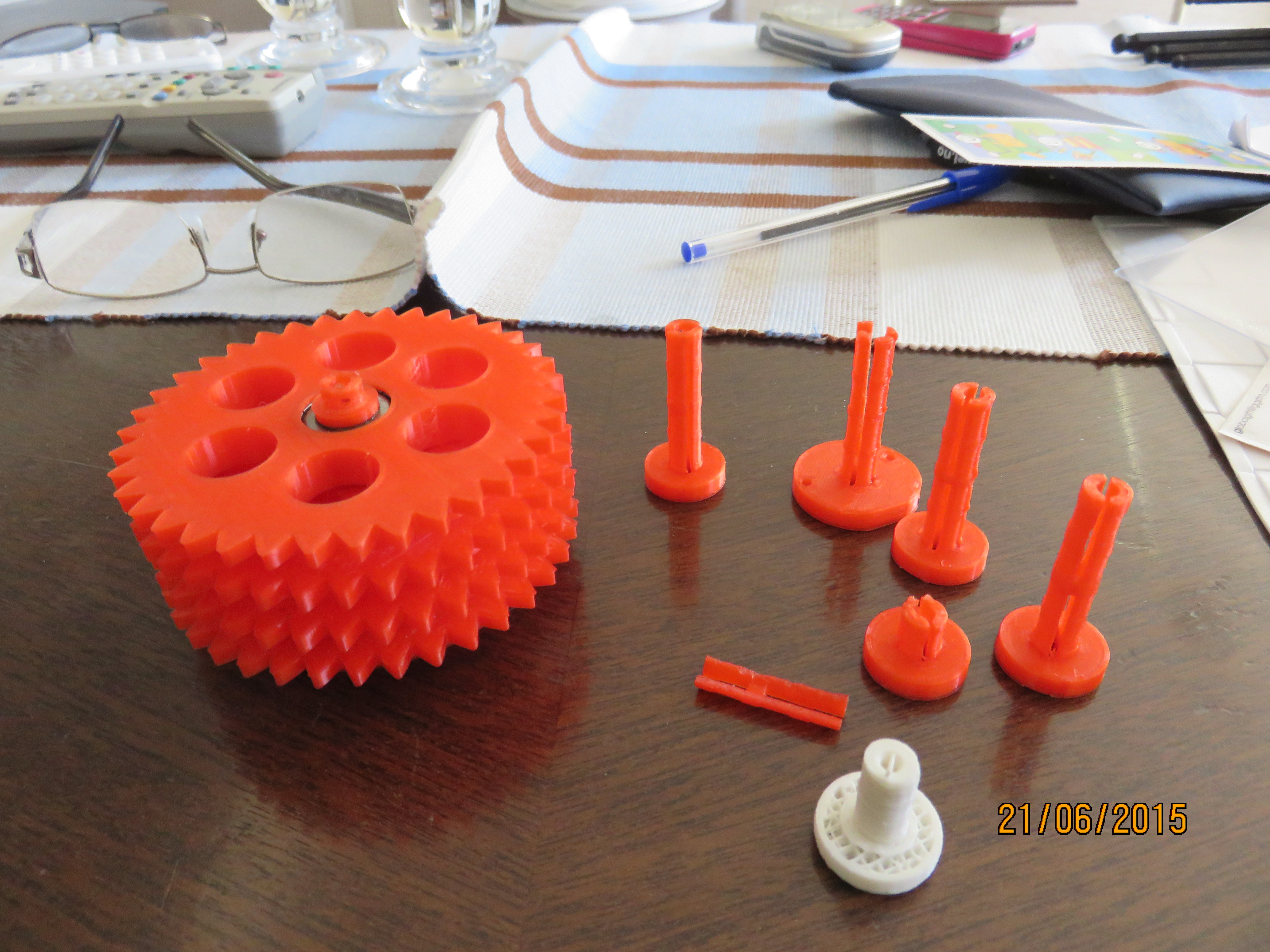
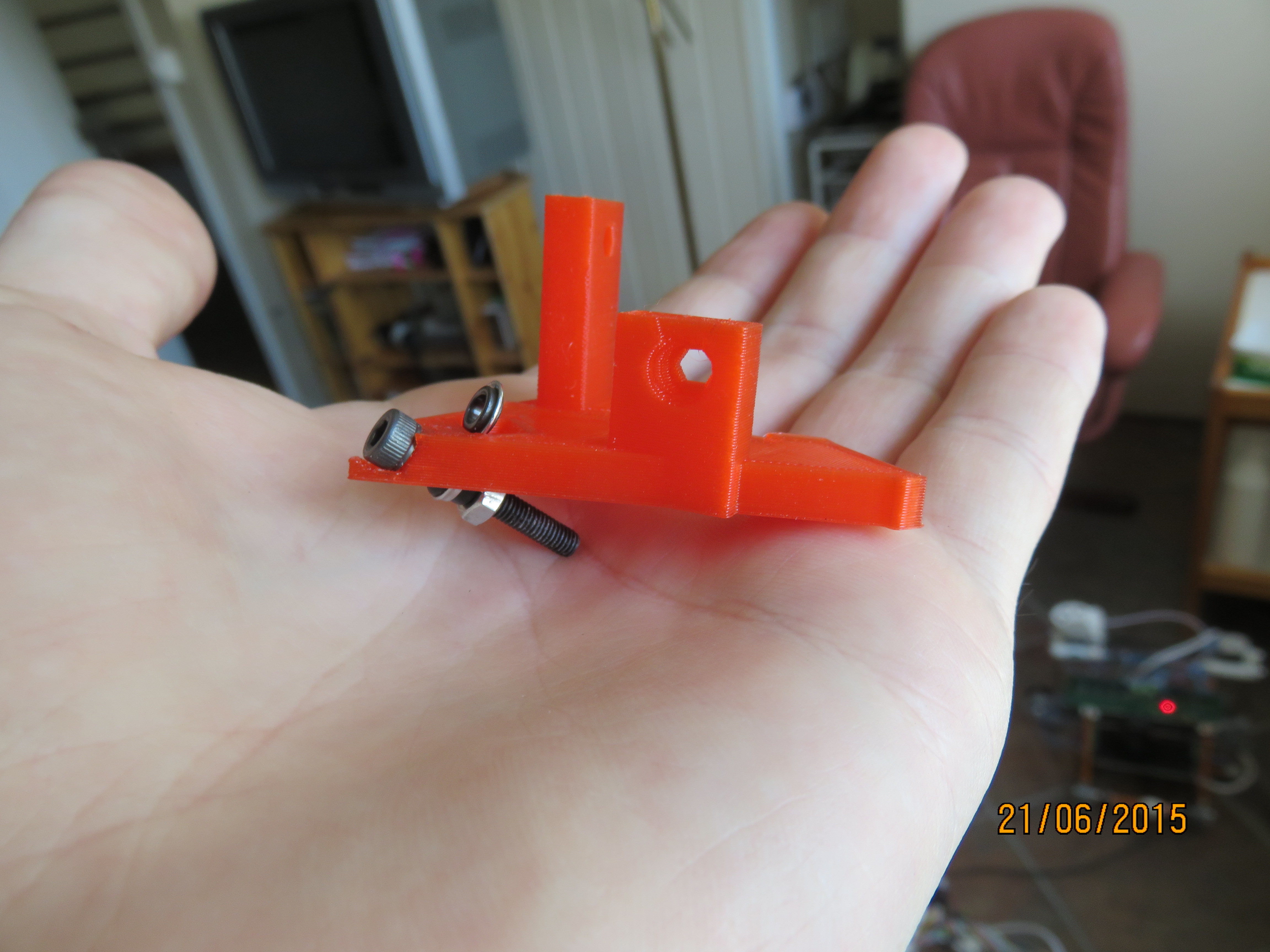
Test Printing
A complete print of Hangprinter is still not done, but many parts are printed for testing. The parts that have been test-printed are the cylinder holding the largest gears in place, the largest gears themselves, the motor gears and the outermost corners of the printer (called bottom_plate in the scad-files).
E3D Sponsoring
I watched an enlightening hot end talk recently, that the E3D-guys held at the Midwest RepRap Festival 2015. In the middle of the talk, they say: "If you're doing a thesis or anything, just get in touch, we'll give you free stuff. We want to encourage such." Since they happen to be the only company I know that produces hot ends specialized for very high extrusion rates, and since they get excellent reviews, I decided to break my shyness and ask kindly for a Volcano Power Pack. The E3D guys were very positive, and gave me a large diameter hobbed bolt and some extra filament as well =D
So I'm designing Hangprinter to fit with a E3D V6 hot end by default.
If you're not familiar with it, check out Tom's reviews on Youtube:
Tom's review of E3D V6
Tom's review of Volcano
That's all for today!
- tobben
The Hangprinter
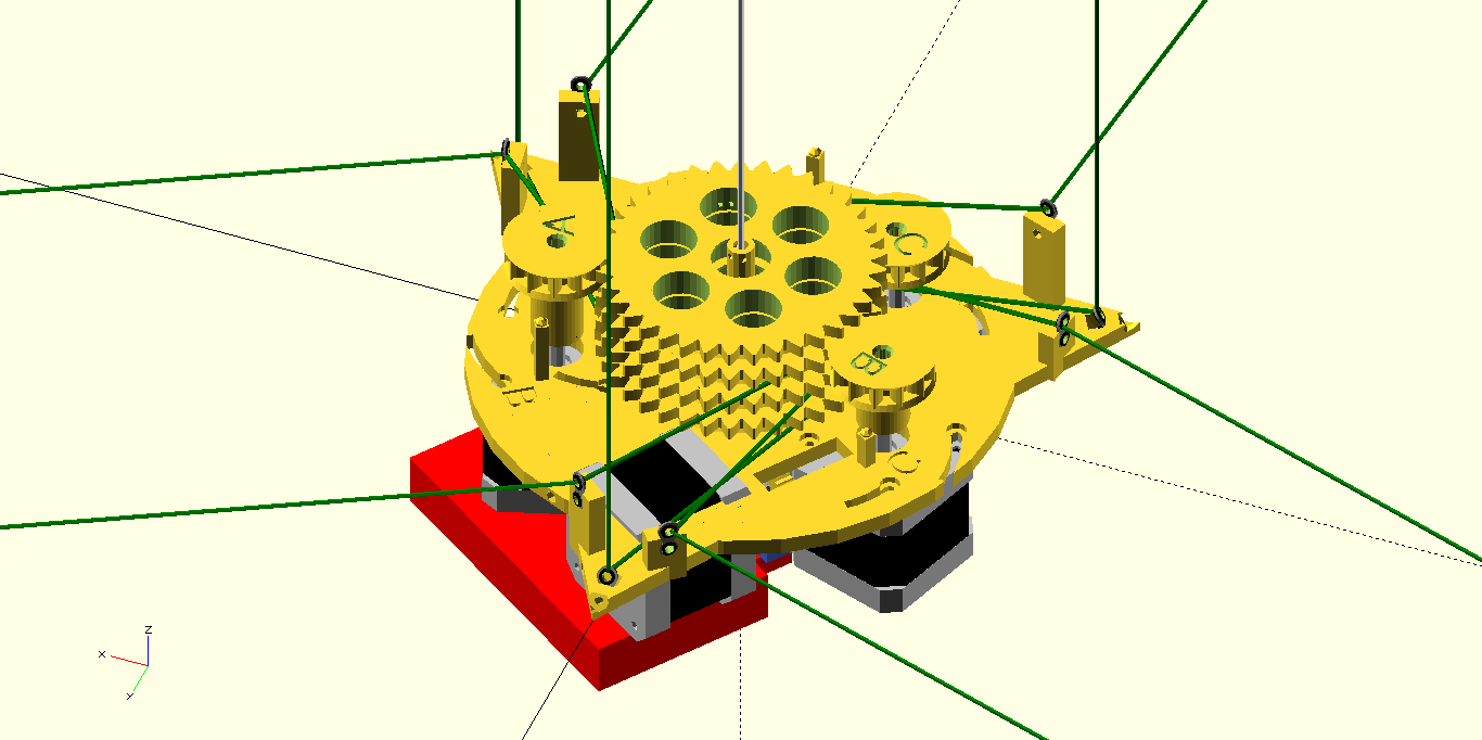
Hi all! There has been some progress on the Hanprinter project this spring as well. The printer is not hanging there, but it soon will. A CAD model has been created:
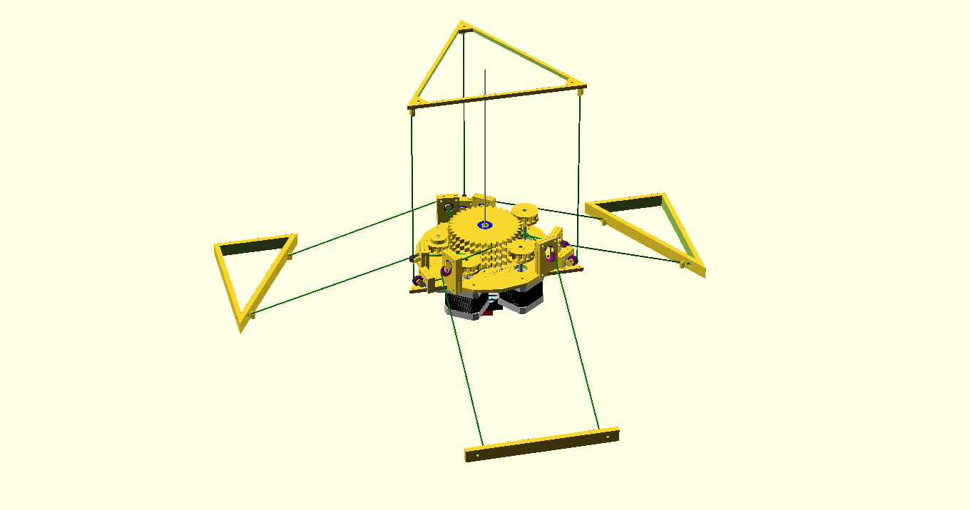
And some parts have been printed:

Finding a Neighbourhood
The project will have its home at the Chalmers Robotics' lab in Johanneberg, Gothenburg. (Drop by if you're in town and in for a coffee and a chat!) The lab is a very special place with 4 m headroom, thousands of soda-cans stacked up, dozens of computer screens, mystical electrical components from another era lying around everywhere, expensive tools like lathe and bandsaw available at any time and skilled hackers and robot builders hanging around 24/7. And best of all: another parallel cable driven robot is being built there right now, so Hangprinter can grow up with a friend in the close neighbourhood.
Main idea
The printer will try to live up to the RepRap projects original objective of trying to build a robot that is as self replicating as possible. My favourite way of putting this is something like: Every Hangprinter owner should be able to make another Hangprinter.
I'll try to make separate posts adressing some mechanics, firmware, project background/motivation and general progress. Please visit the forum thread for discussion and the repo for source code!
All the best!
- tobben
The Slideprinter
There have been some progress on the Hangprinter project this winter. Well, the progress is as small as the number of hours that have been put into it, but if we put the optimistic glasses on, we can say gone from 1d to non-trivial 2d movement.
The firmware that Slideprinter is currently running is a very slightly modified version of Marlin
with the following lines of code added to the function calculate_delta:
  delta[X_AXIS] = sqrt(sq(delta_tower1_x - cartesian[X_AXIS])
                     + sq(delta_tower1_y - cartesian[Y_AXIS])
                     - sq(AZ - cartesian[Z_AXIS]))-DELTA_RADIUS;
  delta[Y_AXIS] = sqrt(sq(delta_tower2_x - cartesian[X_AXIS])
                     + sq(delta_tower2_y - cartesian[Y_AXIS])
                     - sq(AZ - cartesian[Z_AXIS]))-DELTA_RADIUS;
  delta[Z_AXIS] = sqrt(sq(delta_tower3_x - cartesian[X_AXIS])
                     + sq(delta_tower3_y - cartesian[Y_AXIS])
                     - sq(AZ - cartesian[Z_AXIS]))-DELTA_RADIUS;
Note that this code will only handle relative moves correctly. This code affects the max speed of the printer since Marlin (Delta conf) chops straight lines into a hard-coded number of line-segments per second. Since Slideprinter doesn't have enough accuracy or precision for this to matter, I've put number of line segments to 20 (which is small).
I also filmed Slideprinter as it moved. Sorry for the darkness. Vimeo.
EDIT 8-3-2015:
Made a new video:
Vimeo.
- tobben
Links
Hangprinter Campaign: Bountysource Salt
Hangprinter Merchandise USA: Spreadshirt.com
Hangprinter Merchandise Sweden: Spreadshirt.se
Hangprinter Project: [1], [2], [3], [4], [5], [6], [7], [8], [9], [10], [11], [12], [13], [14], [15], [16], [17], [18], [19], [20], [21], [22], [23], [24], [25], [26], [27], [28], [29], [30], [31], [32], [33], [34], [35], [36], [37], [38], [39], [40], [41], [42], [43], [44], [45], [46], [47], [48], [49], [50], [51], [52], [53], [54], [55], [56], [57], [58], [59], [60], [61], [62], [63], [64]
Hangprinter Project Homepage: hangprinter.org
Print Issue Solution Filter Project: [1], [2], [3], [4]
Sourcing RepRappro Mendel in Larvik: [1], [2], [3], [4], [5], [6], [7]
Archive: 2014, 2015, 2016, 2017, 2018, 2020
Github Profile: link
Gitlab Profile: link
Hangprinter project on Gitlab: link
Vimeo User: link
Youtube User: link
Twitter User: link
Master's Thesis: link
Linkedin Profile: link
Appropedia User: link
RepRap Forums User: link
Forums threads: Hangprinter version 1, Hangprinter version 2, Hangprinter version 3, List of Hangprinter threads
Source for this blog: Gitlab repo
Everything on this homepage, except the videos, is licenced under the Gnu Free Documentation Licence. The videos published via Vimeo or Youtube are also licenced via Vimeo or Youtube.