Compensation May Allow Bigger Prints
The line compensation code may increase print volume noticeably. During testing, it has allowed Hangprinter version 2 to go places where version 1 surely would have over-tightened lines and skipped steps.
- tobben
Compensating Line Buildup on Spools
I've added to Hangprinter-Marlins some code that compensates for line buildup on the spools. Without it, I found that error in steps/mm grew to several percent as print dimensions grew close to 1 m. The problem was particularly noticeable on the D-axis since it has three doubled lines, so moving 1 mm in the D-direction puts 6 mm of line on the D-spool.
The approximation of new spool radii that I've used looks like this:
\begin{equation} \frac{\gamma\cdot g}{\sqrt{\beta(l_0 + \omega(D_0 - D)) + r^2}}, \tag{*} \label{*} \end{equation}
where
- \(\gamma\) is the number of motor steps required to rotate the spool 1 radian,
- \(g\) is mechanical advantage (2 for doubled lines),
- \(\beta\) is the volume taken up by 1 length unit of line divided by \(\pi\) and the spool's height,
- \(l_0\) is the length of the line on the spool when printer is home (in origo),
- \(\omega\) is the total number of lines along a direction (3 doubled lines \(\Leftrightarrow\) 6 lines),
- \(D_0\) is the distance from an anchor point to an action point when at home,
- \(D\) is the current distance from anchor point to anchor point and
- \(r\) is the spool's radius when there is no line on it.
Setting these variables will require some measuring and messing around in Configuration.h.
The comments in Configuration.h are honestly trying to be helpful.
The above equation requires quite a bit of computation. If an Atmega2560 running Hangprinter-Marlin were to perform it more frequently than ~10 times per second, it would risk computing new movements slower than it performed them, leading to unwanted print pauses and jerky movements.
To limit the computational load Hangprint-Marlin is currently only computing new steps/mm once per received G1 or G92 commands. A gcode file with 300 G1 movements would cause Hangprinter-Marlin to compute new steps/mm 300 times.
Computing steps/mm only once per movement is of course an approximation. We will only get steps/mm right at exactly one point along the G1-move. It is tempting to place this point at one of the ends since that would be computationally cheap. However, it would kill precision, even for simple movements like the following
  G92 X0
  G1 X100
  G1 X0
The printer would use different steps/mm settings for the two different G1-moves. It would not end up where it started.
Instead of correctness at endpoints, Hangprinter-Marlin computes steps/mm to be correct at the middle of every G1 move. This solves the trivial example of back-and-forth movement described above, but it is still an approximation. The next theoretical step will be to find an equation describing the error we accumulate from not continuously computing new values for steps/mm.
If you want to improve the approach to dynamic steps/mm I've described above,
then you will most probably want to improve lines 1757 to 1763 in Marlin_main.cpp:
    float halfway_delta[4];
    float halfway[3];
    for(int8_t i = 0; i < 3; i++){
      halfway[i] = current_position[i] + 0.5*difference[i];
    }
    calculate_delta(halfway, halfway_delta);
    update_axis_steps_per_unit(delta, halfway_delta);
I've taken the liberty to highlight variables and functions with the colors blue and purple. See master branch in the repo to fetch the code.
- tobben
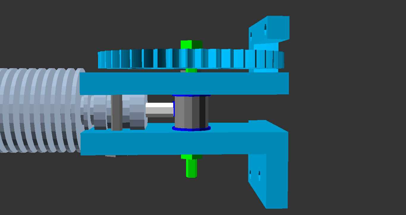
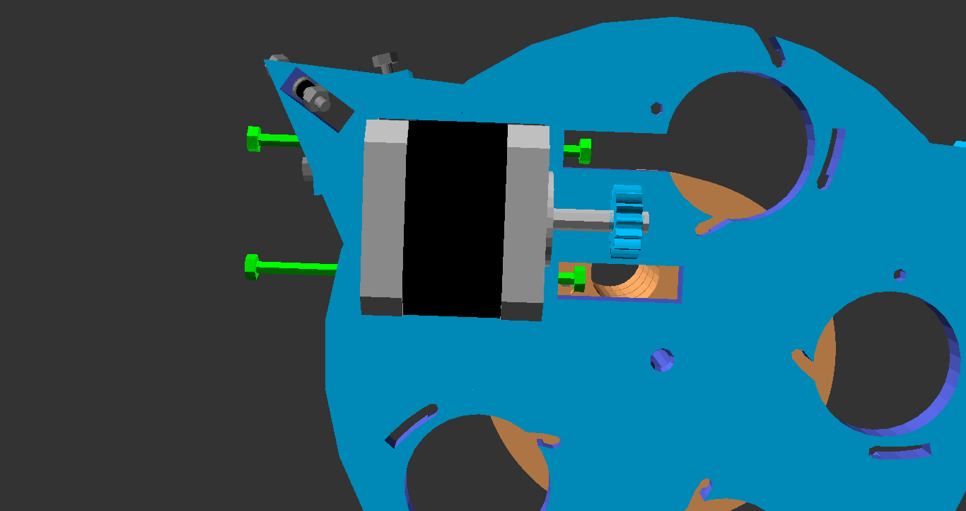
The Worm Drive Works
Just tested the worm drive. I was so happy to see it work that I made a little video.
Thanks to Simon, Jens and strangers at 3D-printerfestivalen for suggesting a worm drive. The worm itself is printed in nylon by Simon.
- tobben
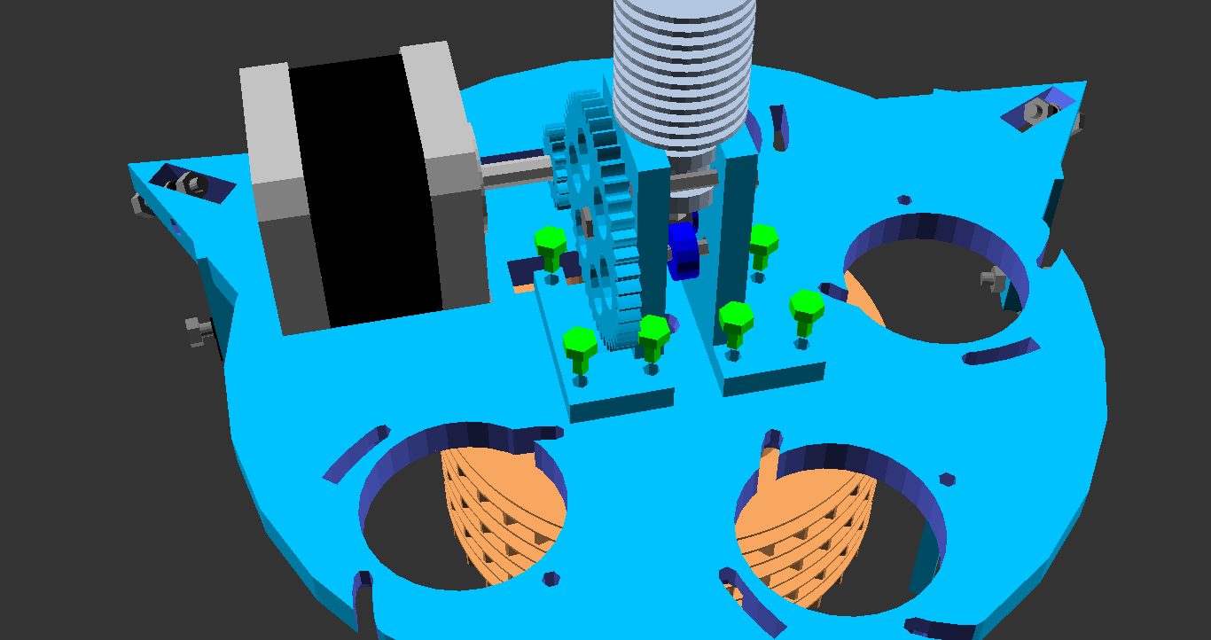
Adjustable D Line Lengths and New Look
Just made the D-line lengths easier to adjust independently. This is useful to get Hangprinter's corners in level with bed. Newest changes are at a new branch in the repo.
I'll be testing out d-line-adjustment, worm drive and new extruder with a physical prototype. Decided to celebrate by creating an alternative look. It saves some plastic too.

linear_extrude().
Cheers!
- tobben
Worm Drive on D-axis
Click on gif to make it stop rotating.


Check out all improvements at worm_and_direct_drive branch in repo.
- tobben
Another Stop Motion Video
- tobben
Hangprinter Calibration Manual v0.1
NOTE from Jan 25, 2018: This manual was created for a very specific version 2 setup, and is served for historical interest
only. For actual calibration in 2018 and onwards, do not use the equations in this post. See this page to learn how to measure ANCHOR_ABCD_XYZ directly instead.
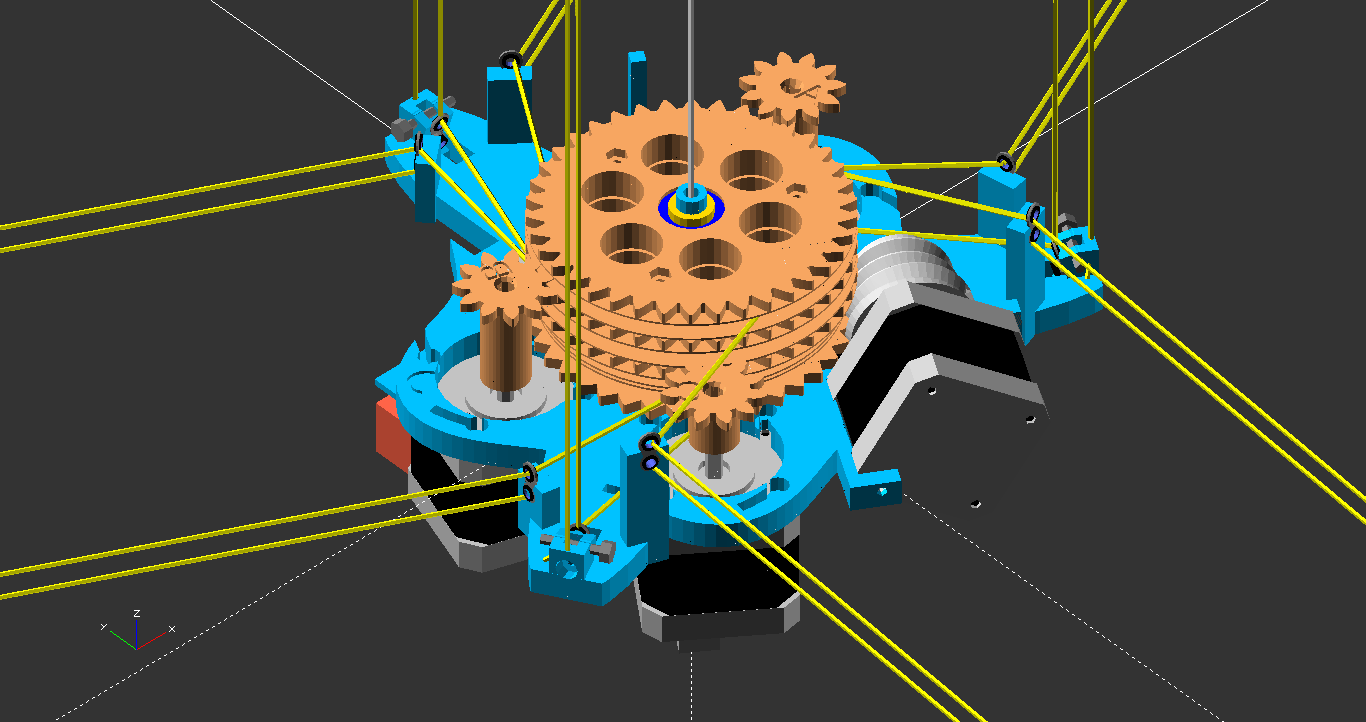
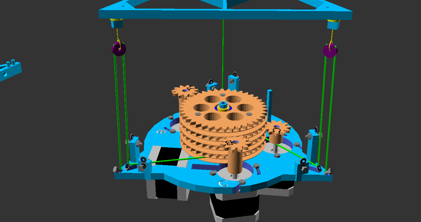
This post will make it easier to calibrate Clerck by avoiding the need for measurements like this:
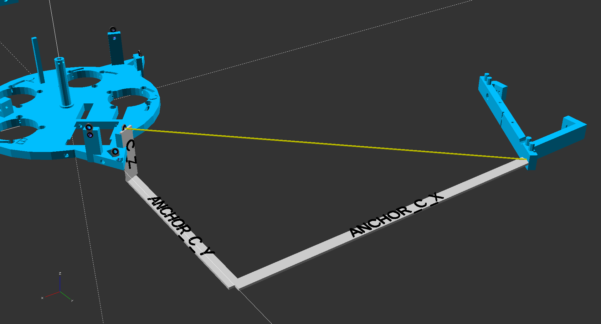
C_Z, the dangling Hangprinter is hard to fixate, and the point where
ANCHOR_C_Y and ANCHOR_C_X meet is hard to determine.
(Se Step 16 in Clerck Assembly manual v0.1 for another figure.)
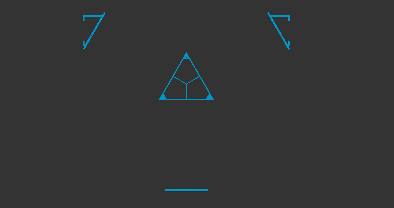
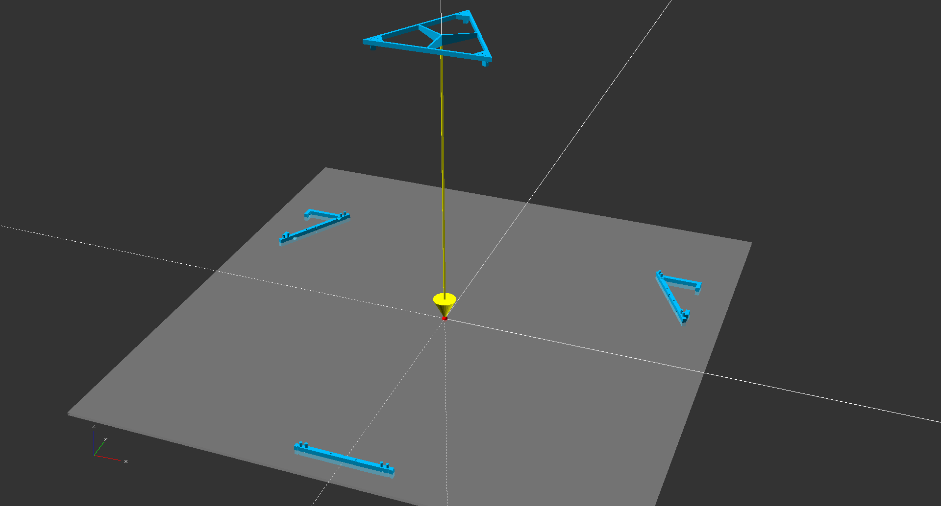
Step 0: Mount Wall Frame Parts
Mount all the lower frame parts at roughly equal heights above your floor. While not theoretically necessary, this makes calculations and measurement procedures easier. We assume your floor is perpendicular to gravity.

Keep the flat sides of lower frame parts as parallel to the ceiling frame part's sides as you can.
Step 1: Mark out Origo in XY-Plane
Use tape or ink to mark out a point directly below your ceiling frame part. This point will be used for measurement and homing reference, so keep it fixed and visible.
Step 2: Measure Six distances

d is equal to the length of the aiming plumb in Figure 3.
Step 3: Translate to Cartesian Distances
Now that we use our six measurements to determine six unknowns.
Denoting the x-position of anchor point B like B_x, we can list the unknowns:
A_yB_yB_xC_yC_xD_z
We orient our Cartesian coordinate system such that A_x = 0.
Also, we set A_z = B_z = C_z = 0 from the restrictions in step 0 above.
Now the Law of cosines
and good old Pythagoras solves the rest for us.
A_y = -aB_y = (s^2 - b^2 - a^2)/(2*a)B_x = sqrt(s^2 - (a + B_y)^2)C_y = (f^2 - c^2 - a^2)/(2*a)C_x = -sqrt(f^2 - (a + C_y)^2)D_z = d
Step 4: Take Action Point Offsets Into Account
Since lines are not tied to the center of hangprinter we need to subtract the offsets.
These numbers are more or less hard-coded into the
OpenSCAD files.
I made a branch called calibration_manual_0
that corresponds to the renderings in this post.
I'm also listing the values for ya right here. Yeah, right here:
ANCHOR_A_X = 0ANCHOR_A_Y = -(a - 59.8)ANCHOR_A_Z = -146.4ANCHOR_B_X = B_x - 59.8*sqrt(3)/2ANCHOR_B_Y = B_y - 59.8/2ANCHOR_B_Z = -136.6ANCHOR_C_X = C_x + 59.8*sqrt(3)/2ANCHOR_C_Y = C_y - 59.8/2ANCHOR_C_Z = -126.8ANCHOR_D_X = 0ANCHOR_D_Y = 0ANCHOR_D_Z = d - 117.0
These values correspond exactly to what you're supposed to feed into Configuration.h
to calibrate your Hangprinter.
In Theory...
We could add three more measurements and be able to calculate A_z, B_z and C_z.
This would get rid of the requirement to mount the lower anchor points in a plane perpendicular to gravity.
I find these three measurements a bit difficult to carry out in practice.
Practical difficulty is of course subjective, but the six-measurement procedure is the one I use.
I hope this has been useful, best of luck!
- tobben
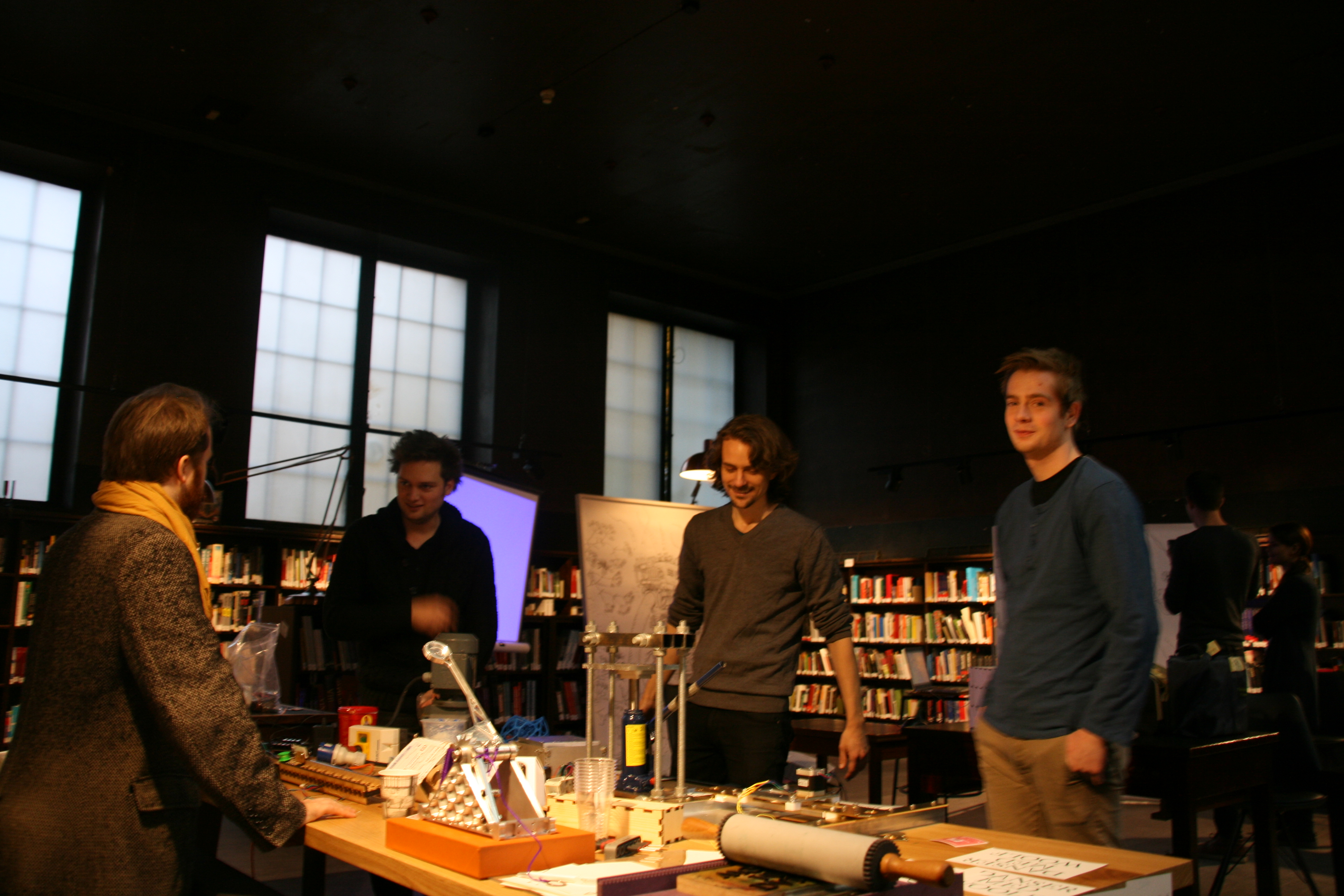
Oslo Skaperfestival 2016
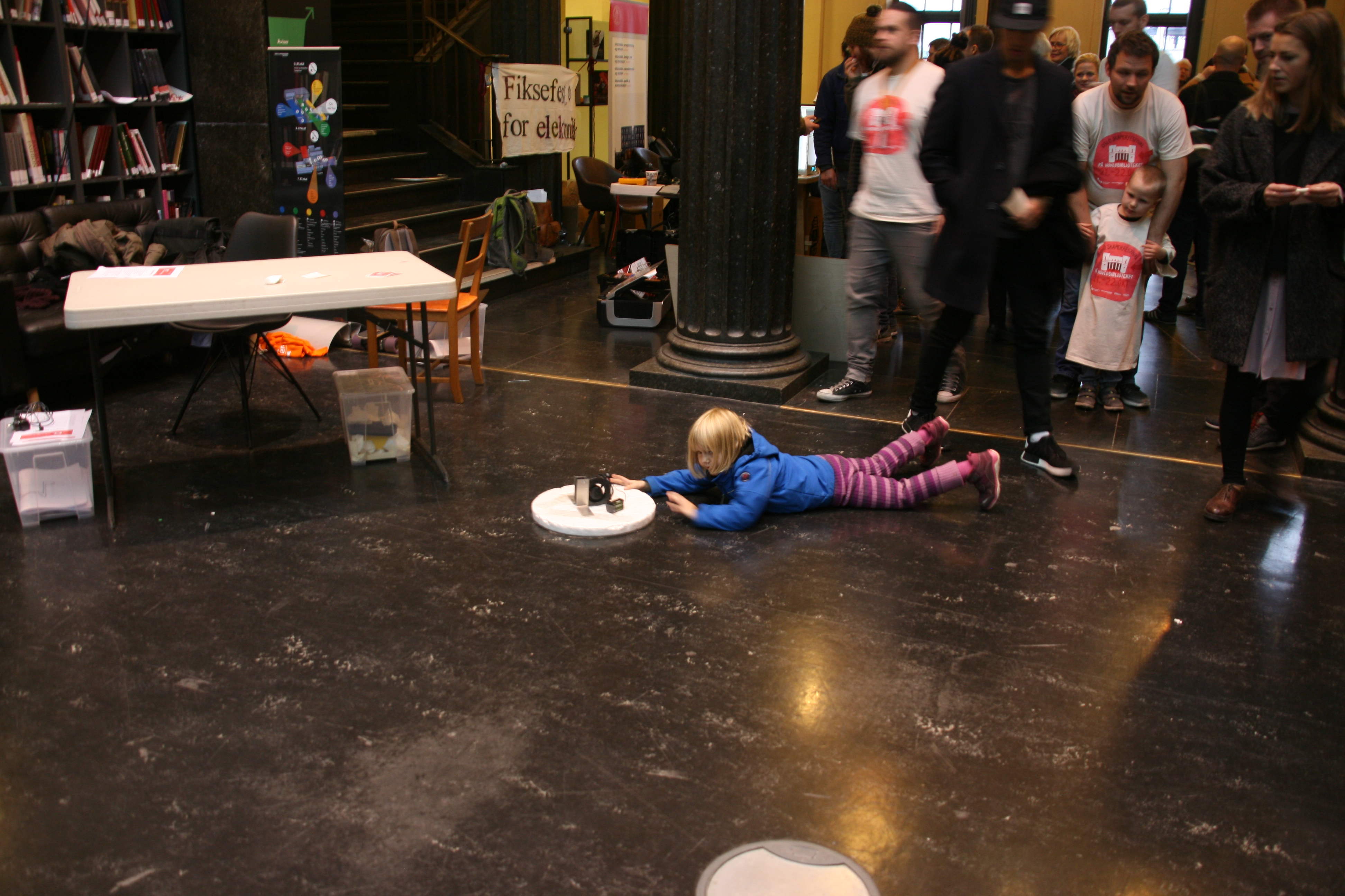
Clerck was demonstrated in public for the first time this weekend!

Fellesverkstedet Fablab and Bitraf Makerspace kindly let me show Clerk by their stand at Oslo Skaperfestival. They even helped me mount and present it! Special thanks to Jens, Martina and Jon for the invitation, the warm welcome and help of various sorts.
The festival atmosphere changed like in a cafe district in April. Sometimes library quiet, doors closed, a few people carrying chairs around. Sometimes tivoli hectic with makers, teachers, hosts, children, amazing machines and zing boom wow bam all along the library hallways.
My work will be influenced by the conversations by the festival stand for a time to come. I'm looking forward to it =)
- tobben
PS! added Oct 26
Here's a layer consistency shot of a print made at Skaperfestivalen. Next time, we're going for something a lot taller!
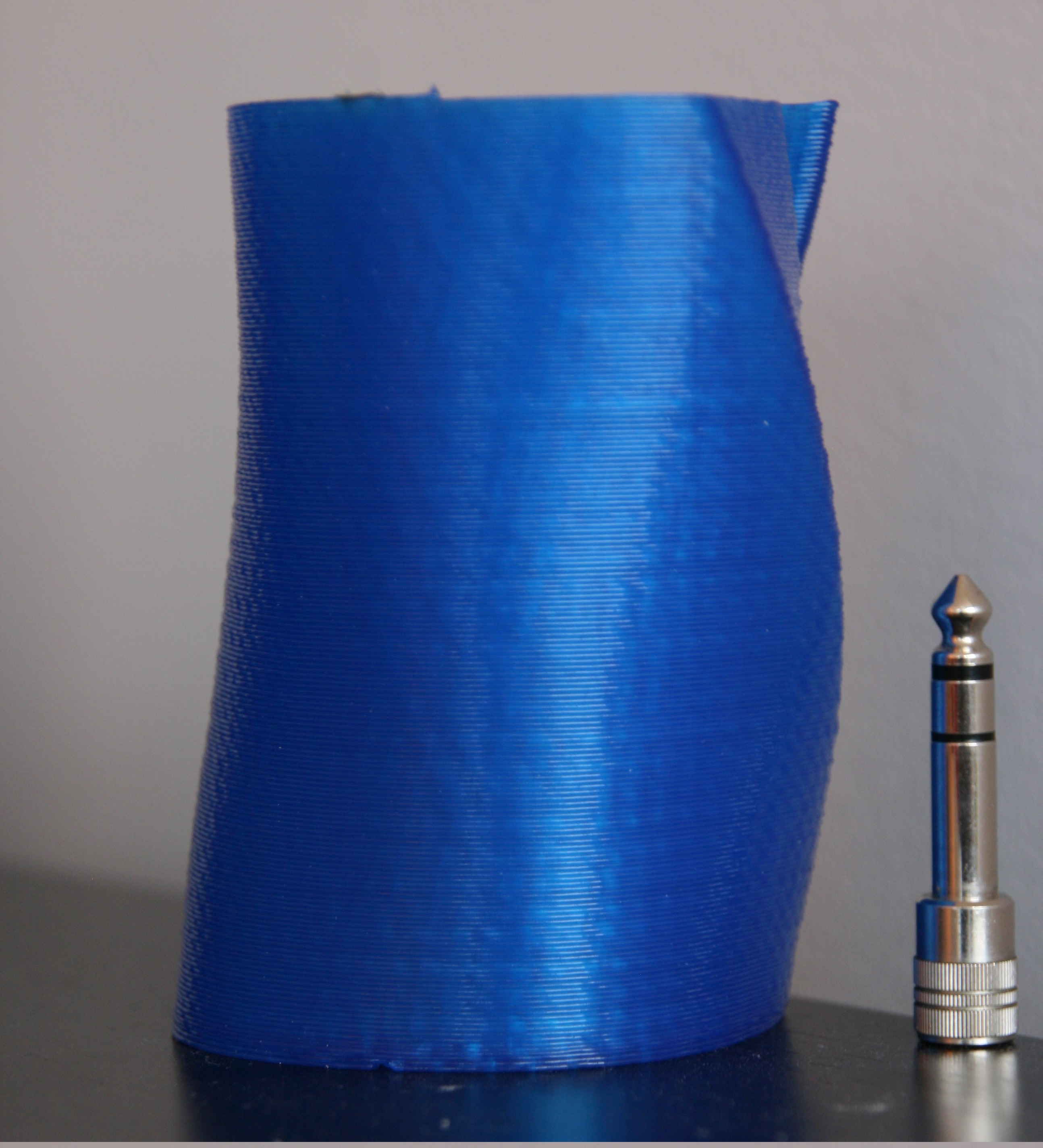
- tobben
Homing the Hangprinter Without Adding Hardware
I've thought some more about Hangprinter recently, since I'm going to demonstrate it on the 3d printer festival arranged by the Norwegian Museum of Science and Technology in Oslo. I've only ever mounted and calibrated Hangprinter once before, so getting the manual homing to work fast enough worries me a bit. I don't have the time to implement the proposed accelerometer dependent homing procedure before the festival.
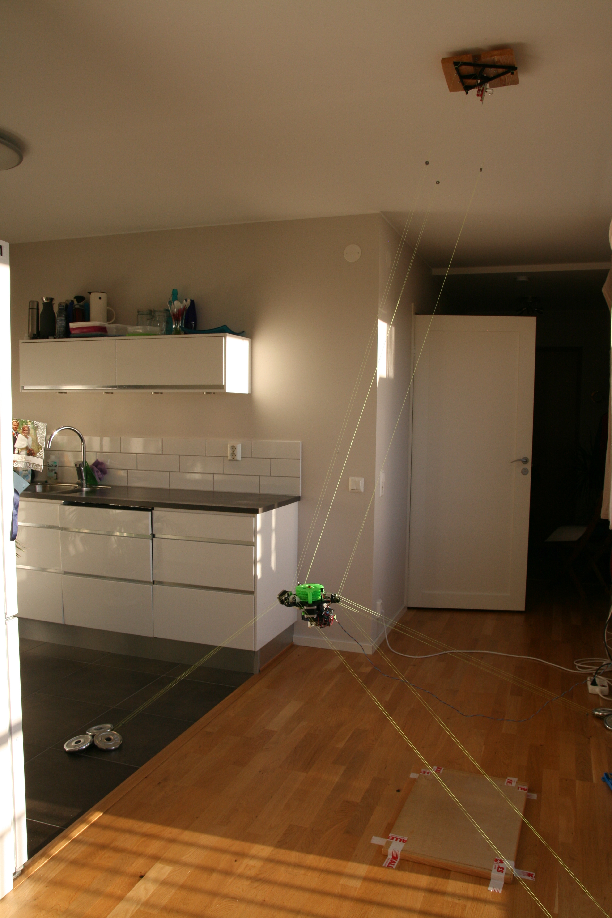
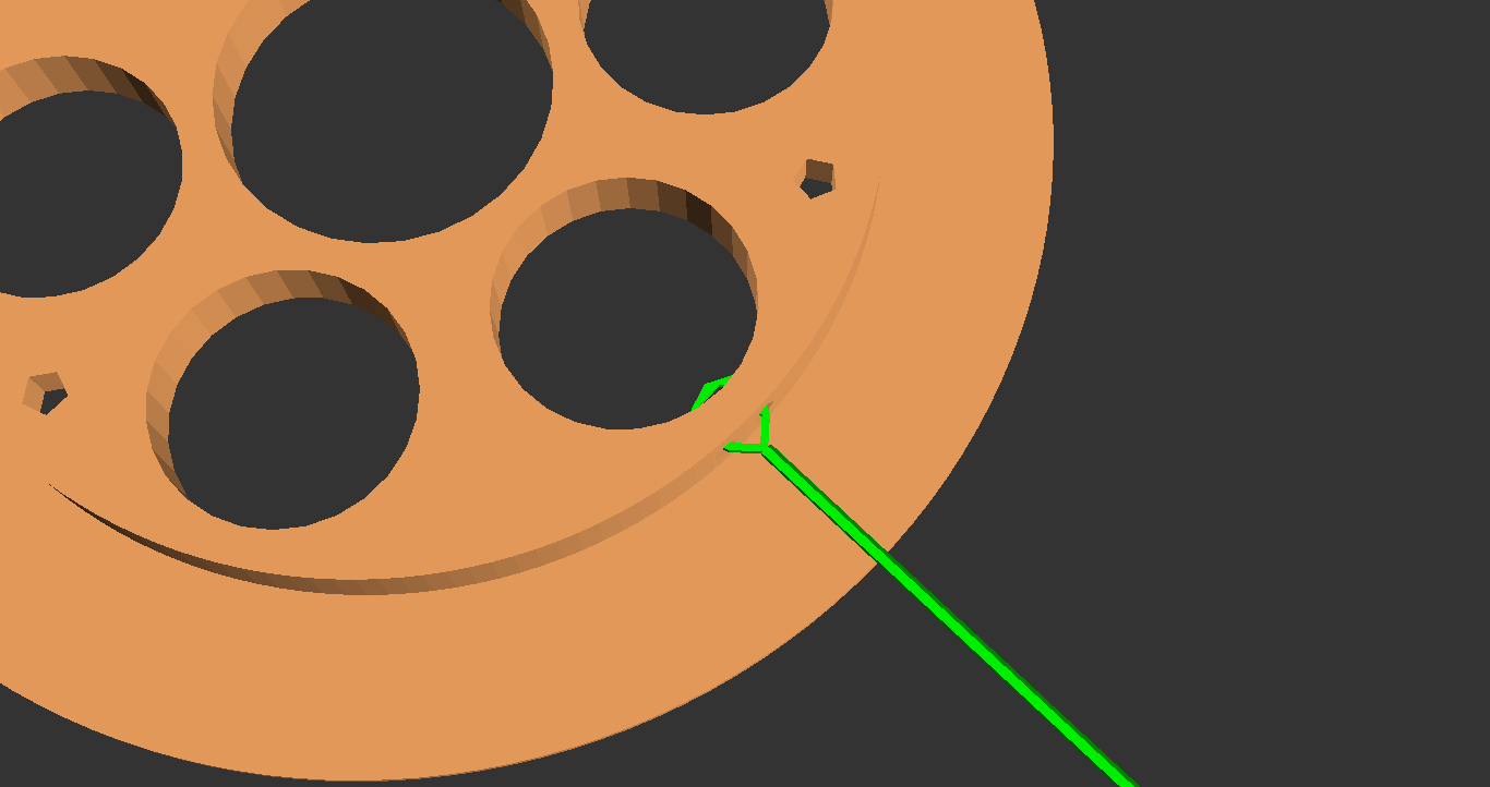
The following (almost stupidly simple but still kind of useful) solution will be the first thing I try to make homing faster than the aiming plump technique I've used before (see picture).
If alignment of marks as shown above proves sufficiently precise, I will use a similar concept for automatic homing. Replacing the green marks with and optical or magnetic sensor arrangement should be quite straightforward.
- tobben
Yet Another Very Simple Extruder Design
I've thought about a second generation Hangprinter lately, including the extruder. My current favourite re-design uses two motors running synchronously.

The motors in the figure above are supposed to resemble Mabuchi 130 servos rather than steppers. The informed discussion in this forum thread and this video demonstration have made me interested in servos again.
The RepRap community's relationship with servos is long, complicated and rather fruitless even though the promise of mechanical simplicity and low weight has always been present. There seems to be something hard about servos. Still, 2d-printer-engineers manages to churn out servo driven movement platforms, lots of them. Are those Inkjet engineers better than us? No, of course not.
Anyways, if the servo usage doesn't pan out at all, I can always try two Nema14's instead. Pinching filament between two motor shafts would still be cool and simple. Not as cool as servos though.
- tobben
Why Optimize Chaotic Production?
RepRappers have noticed me that basing the story line of my my Master's thesis on productivity numbers doesn't resonate with them. This tickled me to think about and formulate why I do what I do, hence this post.
In the thesis, I really wanted to say that we can afford producing in humane, joyful ways, and that D3D-Porteus can help. Also, in this title and previous posts, I have used the word "chaotic" loosely. With chaotic I mean "distributed between people with their own budgets for time and money".
In centralized production, unrelatedness, vulnerability and boredom are hidden costs because they are hard to count but easy to feel. In chaotic production, the producer carries the total production cost, both in time, money and emotion, and also decides how to work and when to stop. Chaotic production must be optimized to meet the producers interests. Optimizing chaotic production must include preserving creative joy.

The answer to the question posed in the title is then the inverse of unrelatedness, vulnerability and boredom, namely:
1: Close Relations
As humans we are evolved to thrive in small groups that help each other. Helpers feel pride and helped ones feel gratitude. It is hard to help and get love in return from distant factories. Producing everything centrally wastes opportunities to feel more pride and gratitude in our lives.
2: Resilience
Centralized factories are single points of failure. Shit just happens sometimes and when it happens we better know how to produce our stuff ourselves.
3: Fun
We are born capable of having interests and we thrive when we get to follow them. Chaotic production doesn't have bosses with the licence to bore. When you're allowed to listen to your heart you will recognize its sense of humour. If you live in an industrialized society you will probably not end up starving in the streets even if you listen to a funny heart.
- tobben
Portable Gcode and Short Status
Today I asked a question on reprap forums that has puzzled me for a long time. Why don't we share gcode instead of 3d models? The technical obstacles are small and it would be an obvious optimization of chaotic production. See the forum post for details. Hoping for an interesting discussion there.
Now that my Master's is finished I'll try to make a living out of it. I'll continue to post report-like documentation here and list day-to-day activities over at my log on the OSE wiki.
As a start, I've co-founded a limited company that is offering RepRap Assembly Workshops and other course activity to schools and youth clubs around Norway and Sweden. See home page in Norwegian here. I tried to make a logo in Blender. It's my first one, and it ended up looking like something you would expect to see on a tube of tooth paste, but I kind of like it because I made it myself:
Before I dive into searching far and wide for jobs, I need to work on my RepRap family in Norway and Sweden. I need people who know RepRap that I can talk with and share knowledge, experiences, hardware and services with. As a start, I'll head to Oslo this week and visit Bitraf and Fellesverkstedet. I hope I can get to know them by helping them with their projects. If they want to cooperate on one of my projects, I plan on suggesting a new D3D-Porteus based on GuixSD, or to work on portable gcode as described in the forum post I posted today.
- tobben
Optimize Chaotic Production
I presented my Master's recently, with a story line that was very RepRap centric. I'd like to re-present and develop my thoughts with some colors here. Be warned that this is a post about why I RepRap, not how I RepRap.
I live in the EU and have a lot of contact with the US. I'm among the lucky ones by all metrics, but I also see a lot of frustration.
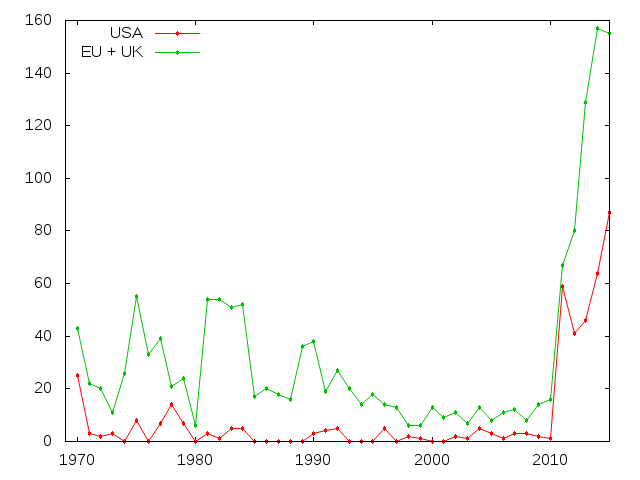

The plots above tell so many stories I, could stare at them for hours. I see how the computer age takes off, and robots starts to produce stuff crazy fast while people go furious. It's like a very odd movie plot, it makes me scratch my head. I've experienced the frustrations of modern western life but I'm surprised by the glaring and obvious stagnation and frustration in the above stats.
EDIT 30 June: There's a really nice presentation of what frustrates western middle classes in this report's Figure 4. The accompanying text explains western middle class stagnation with globalization. It may be right, I don't know what caused what. I just think that our computers and robots should have prevented stagnation regardless. They are so powerful and even supposed to be personal. END EDIT
Computers are machines for thought work, they should lift our burden of thought and give us peace of mind. Well, at least in theory (my dreams)... It would be so nice to just reboot the computer revolution and make it better. Computers could make people independent, resilient, and proud if used right. Like cars do.

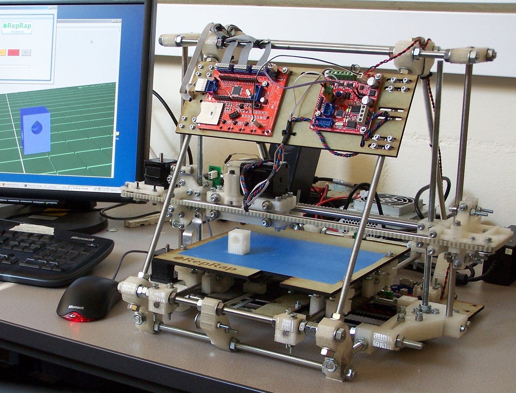
Many are still inspired by T-Ford's successful production style. Bringing a machine to the masses has meant setting up a central production line for at least 100 years, including the years of the recent computer revolution. Only around 2007 was central production first rivaled, by copyability through self-manufacture. The RepRap 3D printers then got so easy to copy, partly thanks to self-manufacturing, that the number of producers grew exponentially.
When rebooting the computer revolution we should try the new RepRap-style of production. In the thesis I show that RepRaps are very popular and numerous. I also show that they are actually produced and forwarded virally. To formalize this observation, I present some data collected by Spanish RepRappers (see Figure 5) and import a structural virality measure used by researchers on other viral phenomena.
In the presentation I point out that chaotic production requires low unique parts count, good documentation and low price, just like assembly line production. I suggest that software freedom and self-manufacture are additional efficiency requirements not found in assembly line production.
I set out to optimize the chaotic and distributed RepRap production and discover that I can do so by optimizing RepRap Assembly Workshops, and particularly the software that they use. I collect all the data I can find about RepRap Assembly Workshop arrangements on the Internet. See my data in good looking pdf here or in practical spreadsheet here.
I end up packaging Marlin, Arduino IDE, Slic3r, Printrun and OpenSCAD in a live OS. Open Source Ecology tested the live OS for me, and they liked it quite well. I've also used it myself in a four-day 3D printing course for kids this summer, and I found it handy. Technical details of the live OS is another post, but files are hosted here.
That was my little story line, hope you liked it and look forward to some more technical stuff in the coming months. Download thesis here, and presentation slides here.
EDIT 30 June: Sorry for messing up the RSS-feed. Restructured the blog to make it load faster. See list of links at bottom of page.
EDIT 7 July: Please use this thread to comment and ask questions related to the thesis or this blog post.
- tobben
Update and Clerck Build Instructions
I've been working on Open Source Ecology 3D printer workshops (see my work log for exactly what I've been up to) the past month, and will continue to work on that until mid summer.
Clerck would love to be developed further by anyone even if I'm on another project right now.
The following instructions should not be considered "the ultimate way", it's simply how I did it on my first try with the
prototype.
The best absolute source of Clerck information is the OpenSCAD files in the Github repo.
A special branch was created for this build manual, called
build_maunal_0.
Hangprinter.scad is the most high-level entry point.
This build manual will be short and terse. Ask questions the forum thread to fill in knowledge and information gaps.
Clerck Assembly Manual v0.1
Step 0: Sourcing
For vitamins bill of materials, see the Appropedia article. Some info on hardware specifics is found in used_hardware directory in repo. For printed parts bill of materials, search stl directory of build_maunal_0 branch in Github repo for the shown STL files. You'll also need the Hangprinter-Marlin firmware. It's in the firmware folder of the repo.
Step 1: Cut Lines to Length and Tie to Spools
Cut all nine lines to desired lengths. If you know the distances between the origin (middle of print bed) and the mounting points (walls and ceiling), then you can use those to calculate good line lengths. I use twice the origin/wall-distance plus ca 1.5 meters along all axes. As there are 4 movement axes on this printer, there will be 4 lengths. We call them the A-length, B-length, C-length and D-length.
After this step you should have:
- 2 A-length lines
- 2 B-length lines
- 2 C-length lines
- 3 D-length lines
Tie the A-length lines onto one spool, then the B-length lines onto another spool etc.
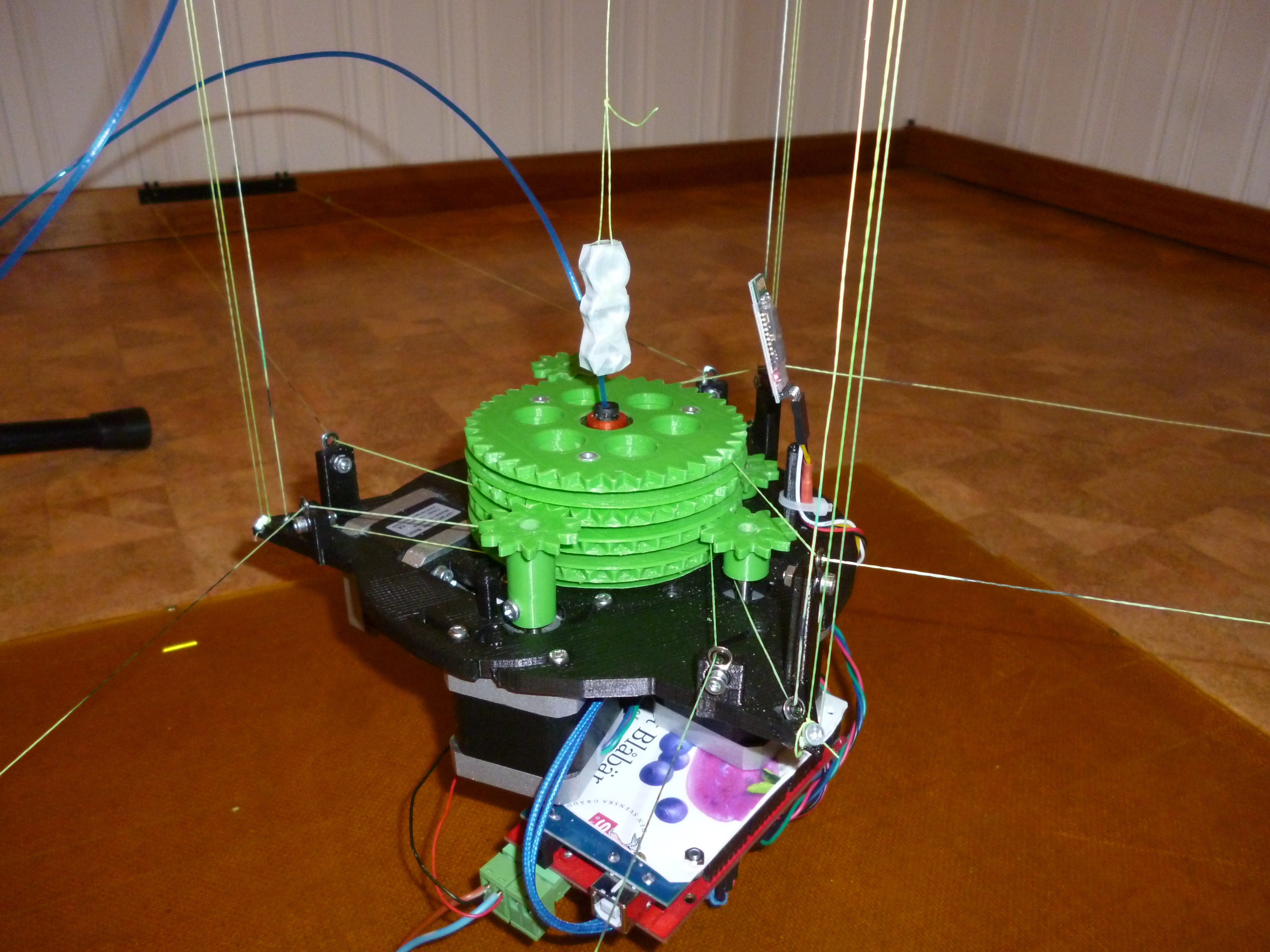
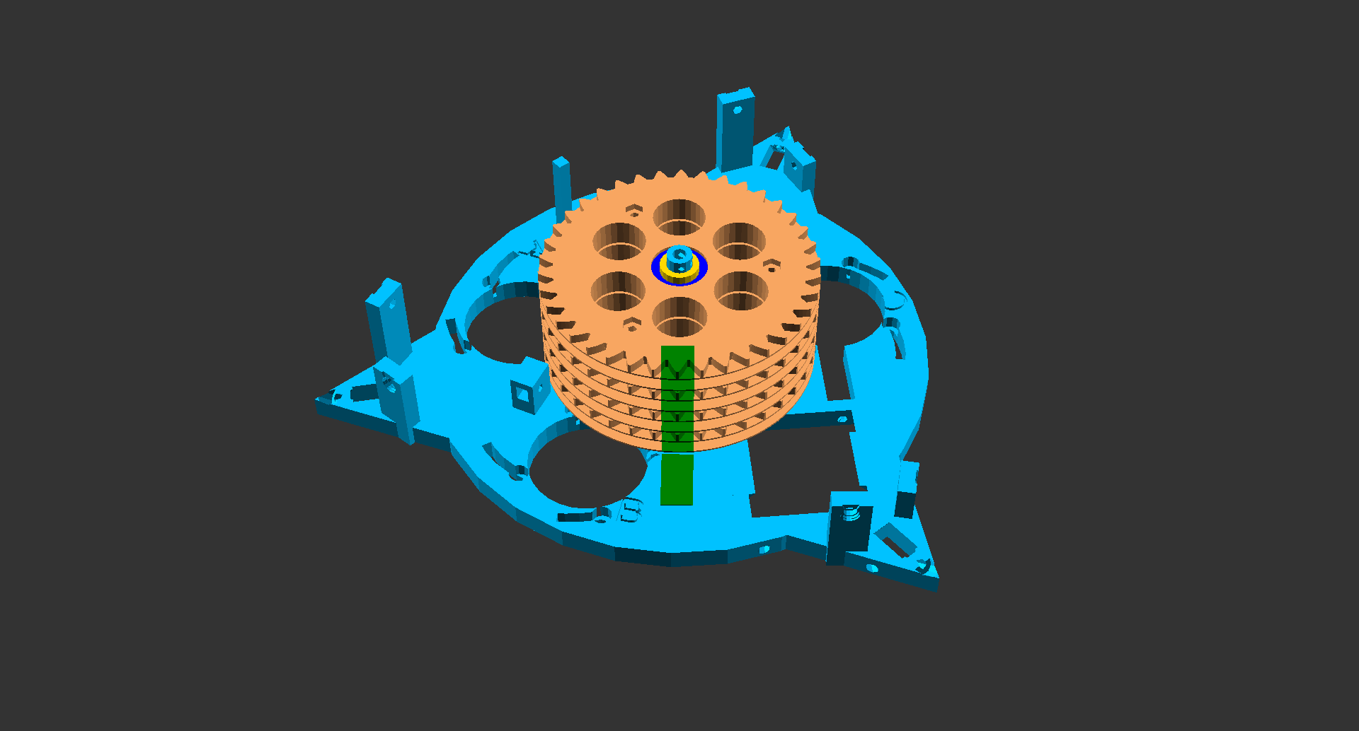
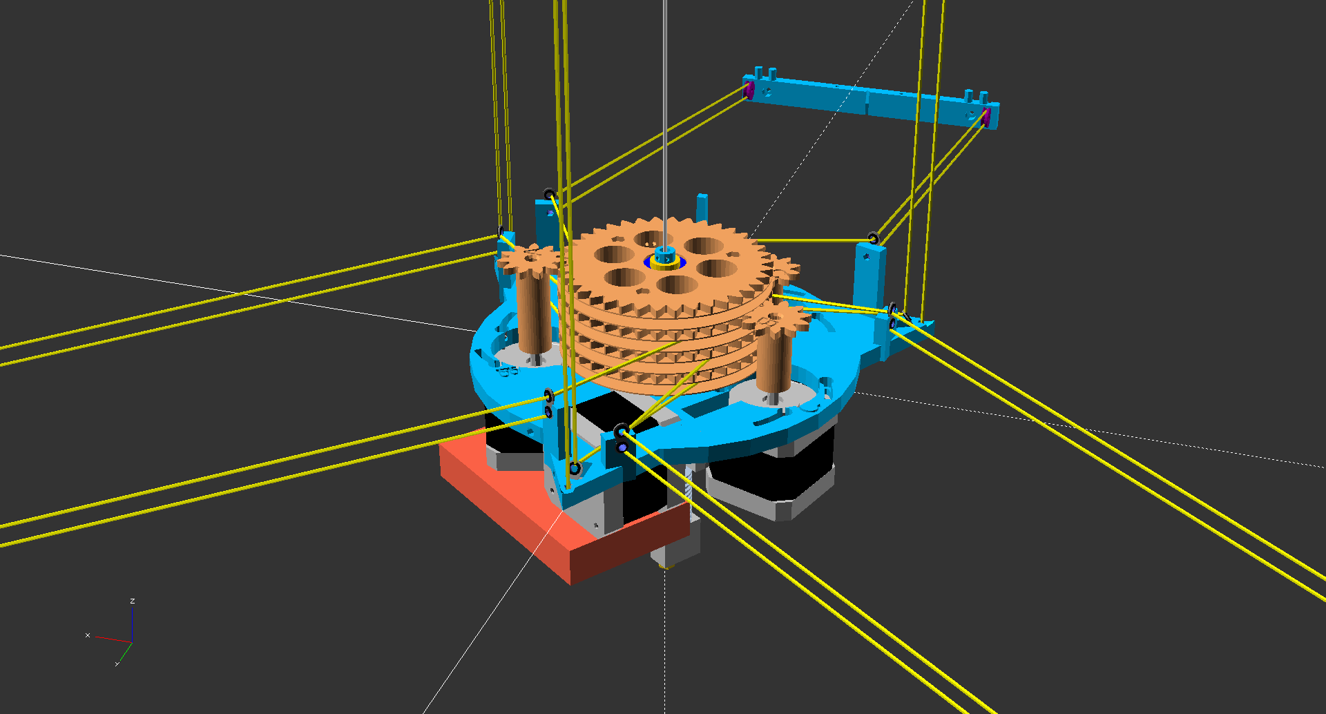
Step 2: Assemble Spools and Gears
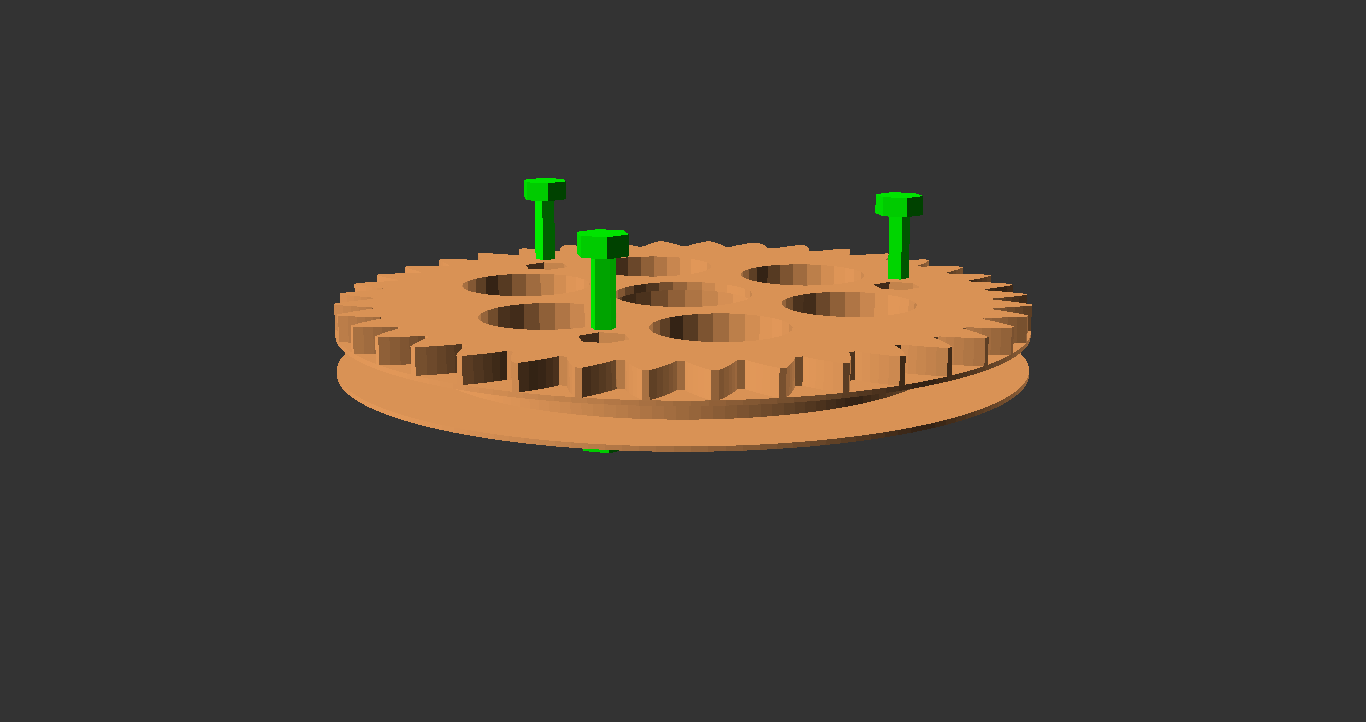
Step 3: Sandwich Spools, Gears, Bearings and Spacers onto Bottom Plate

The bearings and spacers should push-fit onto the middle cylinder of the bottom plate. Ensure that geared spools rotate freely by rotating and wiggling them by hand.
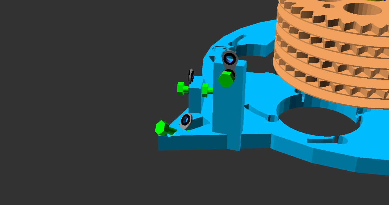
Step 4: Mount Fish Rod Rings and Stop Screw

Step 5: Assemble the Tble-extruder
I used the E3D Volcano as my hot end. Its build instructions are found here. You could use any hot end, but big nozzle diameter and long melt area are key for high print speeds. The Volcano has worked well for me in that it was easy to install, doesn't clog and drools surprisingly little compared to its big nozzle diameters.
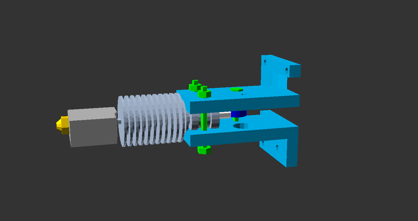
Be warned that the forthcoming alignment task fiddly. If I had any time to work on the Hangprinter project's modules, this extruder would be drastically changed to reduce fiddlyness.
Step 6: Mount Extruder Motor
The small extruder gear is push-fit onto the extruder motor shaft, which should have one flat side. Remove two neighbouring bottom screws from the bottom of the motor before mounting.
Note that this step is very dependent on motor size (maybe unnecessarily so).
If you have another motor than 17HS4401N,
then double check that your motor fits (see lines 2, 3 and 4 in measured_numbers.scad).
The extruder motor hole is created on
line 262 in parts.scad,
if you rather want to change the CAD file than change the motor.
Step 7: Mount Tble-extruder
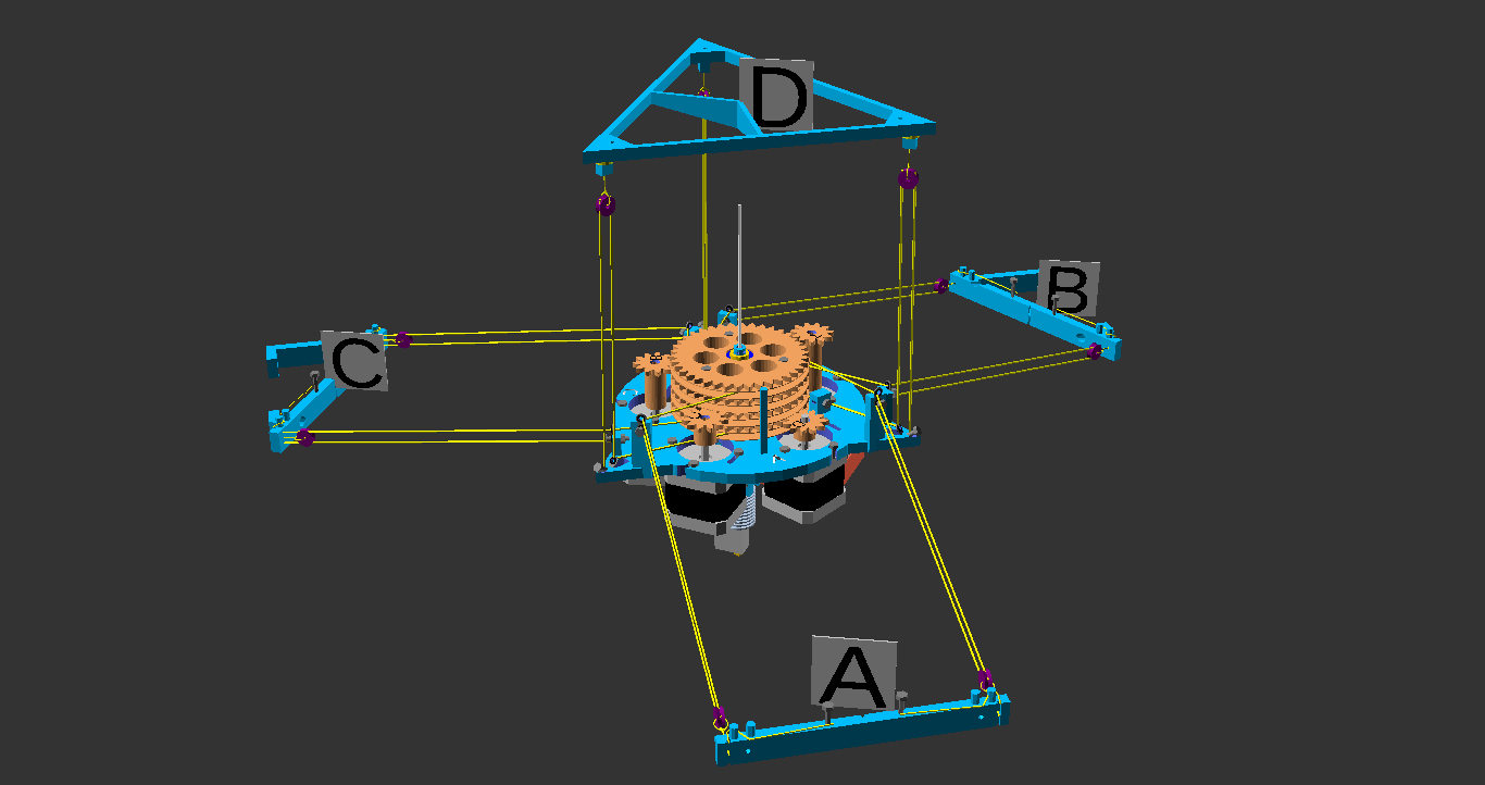
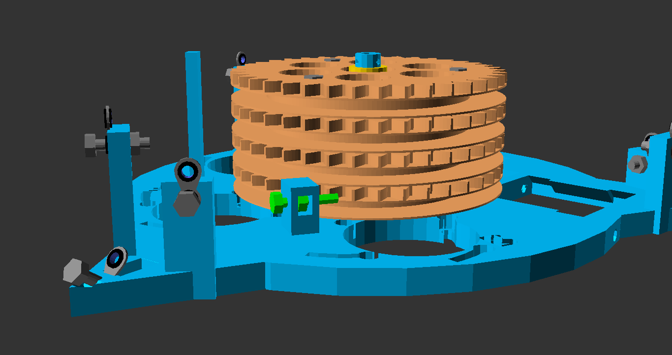
Step 8: Mount the A, B, C and D-motors

Match motor gear height and placement with corresponding spool.
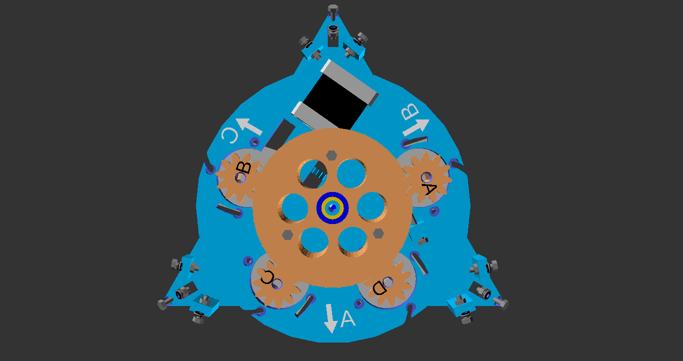
Look at your printer from above to confirm you can read "CBCADAB" from left to right before preceding.

Step 9: Assemble Wall and Ceiling Parts

I hung a wooden platform in a lamp hook avoid having to drill screw holes in the ceiling (see picture).

The end of the A, B and C lines are attached to the M3 screw holding the corresponding fish line ring. More details on that in a previous post.
Step 10: Mount Wall and Ceiling Parts
This is the step where you potentially do screw holes in your walls and ceiling. I use strong double-sided tape for all wall-mounted parts. Placement is really insensitive as long as all plates are, fixed and horizontal. Each side plate should be parallel with one side of the ceiling plate.
Step 11: Thread D-lines
I rested motors on two towers of books while doing this.
Step 12: Mount electronics
Secure locking screw on D-spool-gear and flip the printer upside down. Mount Arduino Mega+RAMPS on an isolating plastic sheet, and mount that sheet using bottom-screws of stepper motors. I used a piece of ice cream packaging as isolation sheet.

Step 13: Upload Firmware
Plug in the USB cable and upload the Marlin firmware found in firmware/Marlin/Marlin.
If you haven't uploaded firmware through the Arduino IDE before, it looks like shown in
this video.
Try to communicate with your RAMPS board through USB cable and
Pronterface (no power supply is needed for this).
Hangprinter-Marlin uses baud rate 115200.
Unplug USB cable when done.
Step 14: Wire up electronics
For those who are new to electronics, take some time to read about general electronics safety. For examle Electronics Safety Rules for Dummies and howtogeek article on static electricity protection. Insulate the hot end. The Clerck design has a high risk of melting its own cables, which will cause fire (see forum thread).
Mount stepper driver chips and adjust Stepstick trimpots to get the right reference voltage (see Tom's video on this and Pololu's product home page). I use Stepsticks with drv8825 drivers, extra long legs and cooling ribs both above and below chip (see previous stuff).
If you connected power to RAMPS during reference voltage adjustment, pull the wall-plug and also unplug power connectors on RAMPS now. Also unplug your USB cable. Wire A-motor to RAMPS's X-contacts, B-motor to Y-contacts, C-motor to Z-contacts and D-motor to E1-contacts. Wire E-motor and hot end as shown here.
If you want wirelessness, wire in the JY-MCY bluetooth antennae as described on the RepRapWiki. Note that the antennae connection will prevent communication through USB cable as long as it is plugged in. I use Blueman Device Manager 1.23 and a Ubuntu 14.04 system for connecting to the JY-MCU.
After doing safety-checks on the electronics and power supply with your multimeter, flip the printer back into upright position and couple the power chords to the RAMPS board. When you're confident that your wiring is right, plug your power supply into the wall and feed your Clerck its first taste of 12V.
Step 15: First Movement
Connect to your Clerck through Pronterface and check that D-motor has a nice constant holding torque.
Unscrew the D-stop screw and watch Clerck hang by itself.
While holding a hand below it, try sending the gcode line G3 D-1.
This tells Clerck to move 1 mm closer to the D anchor point in the ceiling,
without recording or counting the movement anywhere.
Also, ensure hot end temperature readings are sane and try to heat it to say 40 degrees Celsius.
Did it move? Did temp level out at 40? Is it still alive? Sweet Victory!
Now, don't disconnect and reconnect. RAMPS will reset upon reconnection and the D-motor will lose its static torque for a moment. This risks letting Clerck smash into the floor.
The G3-command is very handy for manually homing the printer on startup. Clerck doesn't have automatic homing yet.
Step 16: Measure Lengths to Origin
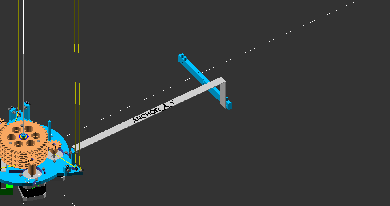
ANCHOR_A_Y of your Clerck setup.
I find careful calibration measurements out in thin air to be the hardest part of a Clerck build.
See lines 96 (#define ANCHOR_A_X) and onwards in firmware/Marlin/Marlin/Configuration.h.
Measure lengths from fish eye to line opening in frame parts.
Arduino IDE can be used to compile and upload Marlin.
For experimentation with line length configurations, use gcode
M665 Q<Ax> W<Ay> E<Az> R<Bx> T<By> Y<Bz> U<Cx> I<Cy> O<Cz> P<Dz>.
Step 17: Thread A, B and C Lines
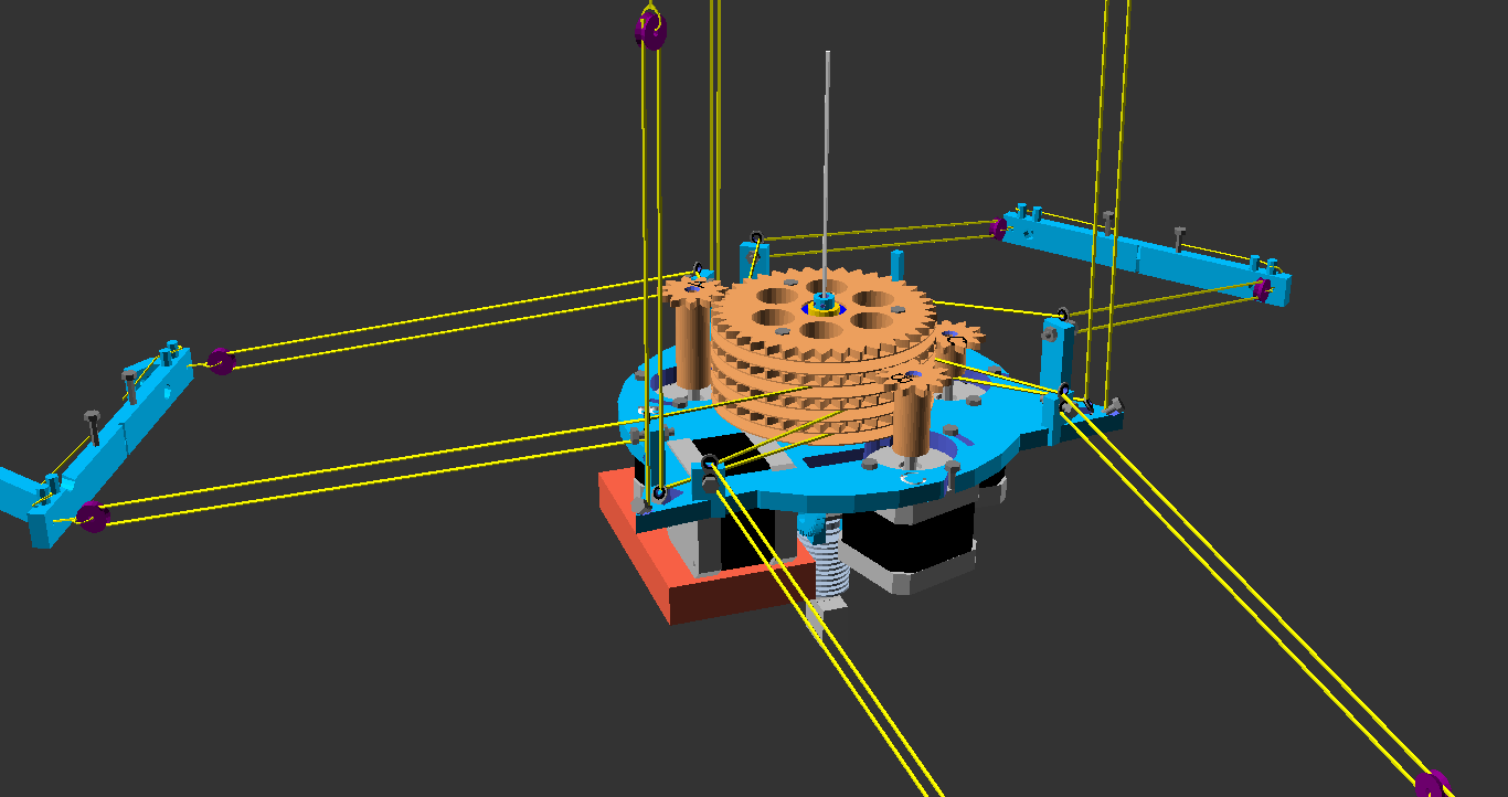
Step 18: Additions to Ceiling Plate
Counterweights
I use ca 250 grams of counterweight attached in each corner, with lines running along the outermost D-lines and running through the same vgroove bearings in the ceiling part.
Manual Homing with Aiming Plumb
I'm simply homing the printer using gcodes G3 (move without recording it) after powering on.
The gcodes G92 and
M114.
To help the manual homing process, I've attached an aiming plumb to the center of the ceiling part, see
picture and previous post.
End of assembly manual. Ask questions in the forum thread about the stuff that is unclear. If you're building version 2 (worm drive, more rounded bottom plate), the forum thread for that one is here. For the files used to create renderings, see branch "build_maunal_0" in the repo (link). Hope you've enjoyed and wish you all happy hacking!
- tobben
Links
Hangprinter Campaign: Bountysource Salt
Hangprinter Merchandise USA: Spreadshirt.com
Hangprinter Merchandise Sweden: Spreadshirt.se
Hangprinter Project: [1], [2], [3], [4], [5], [6], [7], [8], [9], [10], [11], [12], [13], [14], [15], [16], [17], [18], [19], [20], [21], [22], [23], [24], [25], [26], [27], [28], [29], [30], [31], [32], [33], [34], [35], [36], [37], [38], [39], [40], [41], [42], [43], [44], [45], [46], [47], [48], [49], [50], [51], [52], [53], [54], [55], [56], [57], [58], [59], [60], [61], [62], [63], [64]
Hangprinter Project Homepage: hangprinter.org
Print Issue Solution Filter Project: [1], [2], [3], [4]
Sourcing RepRappro Mendel in Larvik: [1], [2], [3], [4], [5], [6], [7]
Archive: 2014, 2015, 2016, 2017, 2018, 2020
Github Profile: link
Gitlab Profile: link
Hangprinter project on Gitlab: link
Vimeo User: link
Youtube User: link
Twitter User: link
Master's Thesis: link
Linkedin Profile: link
Appropedia User: link
RepRap Forums User: link
Forums threads: Hangprinter version 1, Hangprinter version 2, Hangprinter version 3, List of Hangprinter threads
Source for this blog: Gitlab repo
Everything on this homepage, except the videos, is licenced under the Gnu Free Documentation Licence. The videos published via Vimeo or Youtube are also licenced via Vimeo or Youtube.